Product Overview
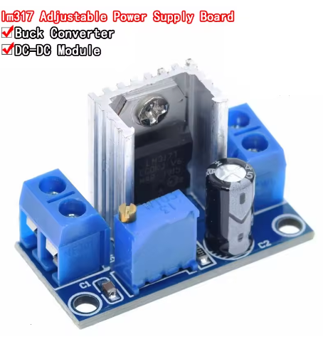
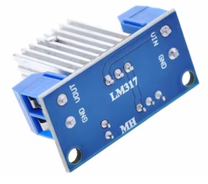
The LM317 Adjustable Regulated Power Supply Module is a compact, high-performance linear voltage regulator board built around the industry-standard LM317 integrated circuit from Texas Instruments . This module provides a simple, reliable solution for converting higher DC voltages into a stable, continuously adjustable lower output voltage, making it an essential tool for electronics hobbyists, educators, and professionals.
Unlike switching regulators that use high-frequency noise, the LM317 is a linear regulator that delivers exceptionally clean and quiet power, making it ideal for powering sensitive analog circuits, audio equipment, and microcontroller-based projects where noise immunity is critical . The module accepts a wide input voltage range from 4.2V to 40V DC and provides an adjustable output from 1.2V to 37V, covering virtually all common voltage requirements for electronic devices .
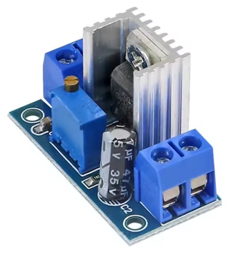
The module features an onboard precision potentiometer for easy voltage adjustment, clearly labeled screw terminals for input and output connections, and an intuitive layout that makes it perfect for benchtop power supplies, battery charging circuits, sensor power sources, and DIY electronics projects. With a maximum output current of 1.5A and built-in thermal overload protection, this module is both versatile and robust .
Key Features
-
Wide Input Voltage Range: Accepts DC input from 4.2V to 40V, compatible with a variety of power sources including wall adapters, batteries, and solar panels .
-
Adjustable Output Voltage: Provides continuously adjustable output from 1.2V to 37V via onboard precision potentiometer, covering common voltages like 3.3V, 5V, 9V, 12V, and 24V .
-
1.5A Output Current: Capable of delivering up to 1.5A of continuous output current, sufficient for most small to medium electronic loads .
-
Low Output Noise: As a linear regulator, the LM317 produces very low output ripple and noise, making it ideal for powering sensitive analog and audio circuits .
-
Built-in Protection Features: Includes current limiting, thermal overload protection, and safe operating area protection to safeguard the module and your devices .
-
Simple Adjustment: Onboard precision potentiometer allows for easy, tool-free voltage adjustment (clockwise to increase, counter-clockwise to decrease) .
-
Screw Terminal Connections: Features screw terminals for input and output connections, allowing for solderless, secure wiring.
-
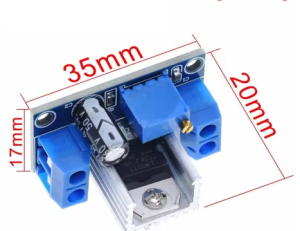
Compact Form Factor: Small PCB footprint (approximately 35.6mm × 16.8mm) allows for easy integration into a wide variety of projects and enclosures .
Technical Specifications
Pinout & Interface Guide
Input Side (Power Source)
Output Side (Load Connection)
User Controls
Note: Input and output grounds are common and connected internally within the module.
Usage Guide
Wiring Instructions
IMPORTANT: Always disconnect the input power source before wiring or modifying connections.
-
Connect Input: Connect the positive wire of your DC power source to the IN terminal. Connect the negative wire to the GND terminal.
-
Connect Multimeter (Recommended): Attach a multimeter to the output terminals (OUT and GND) for accurate voltage monitoring during adjustment.
-
Adjust Output Voltage: Power on the module. Using a small screwdriver, turn the blue potentiometer clockwise to increase output voltage or counter-clockwise to decrease output voltage while monitoring the multimeter .
-
Connect Load: Turn off power, connect your device to OUT and GND, then re-apply power.
Output Voltage Calculation
The output voltage is determined by the formula:
Vout = 1.25V × (1 + R2 / R1)
Where R1 is the resistor between OUT and ADJ, and R2 is the resistance of the potentiometer .
Example Applications
1. Variable Bench Power Supply:
2. 5V Power Supply from 12V Battery:
3. Battery Charger:
-
Connect appropriate DC source to input
-
Set output to battery float voltage (e.g., 12.6V for 3S Li-ion)
-
Use the module’s current limiting capability for safe charging
Important Considerations
-
Linear Regulator Design: This is a linear (not switching) regulator. Excess voltage is dissipated as heat. For large voltage differentials (e.g., 24V to 5V) at high currents, the module will generate significant heat .
-
Minimum Load: For stable regulation, the LM317 requires a minimum output current of typically 3.5mA to 10mA. Very light loads may result in output voltage drift .
-
Input-Output Differential: The input voltage must be at least 3V higher than the desired output voltage for proper regulation . The maximum allowable differential is 30V.
-
Heat Management: For loads above 500mA or large input-output differentials, adding a heatsink to the LM317 IC is strongly recommended to prevent thermal shutdown.
-
Protection Diodes: In battery charging applications, it is recommended to add protection diodes across the input and output to prevent reverse current when the power supply is turned off .
Q: What is the difference between a linear regulator (LM317) and a switching regulator (buck converter)?
A linear regulator like the LM317 provides very clean, low-noise output voltage but dissipates excess voltage as heat, making it less efficient for large voltage drops. A switching regulator is more efficient but can introduce high-frequency switching noise. The LM317 is ideal for sensitive analog circuits, audio equipment, and applications where power efficiency is not the primary concern .
Q: What is the maximum output current I can draw from this module?
The LM317 is rated for a maximum of 1.5A output current. However, for long-term reliability, it is recommended to stay within 1A, and a heatsink should be used for loads above 500mA
Q: Can this module increase voltage (boost)?
No. This is a step-down (buck) converter only. The output voltage must always be lower than the input voltage. The input must be at least 3V higher than the desired output for stable regulation
Q: Why is my output voltage not changing when I turn the potentiometer?
The potentiometer has a wide adjustment range. Turn it multiple rotations in either direction while monitoring with a multimeter. If still not changing, check that the input voltage is at least 3V higher than your target output voltage
Q: The module gets hot. Is this normal?
Yes, linear regulators generate heat in proportion to the voltage drop and current. If it is too hot to touch, you should:
-
Add a heatsink to the LM317 IC
-
Reduce the load current
-
Reduce the input voltage (bring it closer to the output voltage)
-
Ensure adequate airflow around the module
The LM317 dissipates power as: Power (W) = (Vin – Vout) × Iout .
Q: What is the efficiency of this converter?
Efficiency varies based on input and output voltages. Efficiency = Vout / Vin × 100%. For example, converting 24V to 5V is only about 20% efficient. The remaining 80% is dissipated as heat. For high-efficiency applications, consider a switching buck converter.
Q: How accurate is the output voltage?
The LM317 has a typical output voltage tolerance of approximately ±1% when properly configured, with excellent line and load regulation (0.01% and 0.1% typical respectively)
Q: What is the minimum load current required?
The LM317 requires a minimum output current of typically 3.5mA to 10mA for stable regulation. With very light loads (e.g., a microcontroller in sleep mode), the output voltage may rise slightly
Q: The module has power but no output voltage. What's wrong?
Follow this checklist:
-
Check that input voltage is between 4.2V and 40V
-
Verify input voltage is at least 3V higher than your target output
-
Check that the load is not shorted
-
Adjust potentiometer clockwise (may require multiple turns)
-
Verify a minimum load is present (at least 10mA)
Q: Can I use this module to charge batteries?
Yes, with caution. The LM317 can be configured as a constant current/constant voltage charger for lead-acid and lithium batteries. The typical battery charger circuit uses the LM317 with a current-limiting resistor . For unattended charging of lithium batteries, use a dedicated charger module with proper CC/CV charging profile.
Q: Does this module have reverse polarity protection?
Most basic LM317 modules do not include reverse polarity protection. Reversing the input polarity may damage the module. Always double-check your wiring before applying power.
Q: What size heatsink do I need for higher power operation?
For continuous operation above 500mA or with large voltage differentials, a heatsink is recommended. The LM317 can dissipate up to 15W with a 200×200×4mm heatsink
Q: What can I build with this LM317 module?
Popular applications include:
-
Variable benchtop power supply for testing electronics
-
Battery charger for lead-acid, NiMH, and Li-ion batteries
-
Sensor power supply for clean, low-noise 3.3V or 5V
-
Audio equipment power supply where low noise is critical
-
DIY laboratory power supply with voltage monitoring
-
Portable device charger for various voltage requirements
Q: Can I use this module to power a microcontroller like Arduino or ESP8266?
Yes. Set the output to 5V for Arduino or 3.3V for ESP8266. However, be aware of the module’s heat dissipation when stepping down from a high voltage source (e.g., 24V to 5V). For battery-powered applications, a switching regulator may be more efficient.
Q: Can I run two modules in parallel for more current?
Not recommended. Linear regulators do not share current equally when connected in parallel without additional circuitry. For higher current, use a single higher-rated regulator (such as the LM350 for 3A output).
Q: What is the difference between LM317 and LM7805?
The LM317 is an adjustable regulator (1.2V-37V output), while the LM7805 is a fixed 5V regulator. The LM317 offers greater flexibility for different voltage requirements .