Product Overview
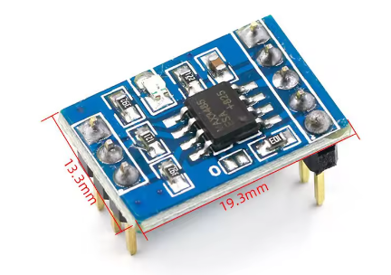
The MAX3485 TTL to RS485 Converter Module is a compact, low-power communication interface designed to bridge the gap between 3.3V microcontrollers and the industrial RS485 serial bus standard. Powered by the MAX3485 transceiver chip from Analog Devices (formerly Maxim Integrated), this module converts standard UART/TTL signals from your Arduino, ESP32, STM32, or Raspberry Pi into differential RS485 signals, enabling reliable long-distance communication in electrically noisy environments .
RS485 is the backbone of industrial automation, building management systems, and multi-device networks. Unlike standard TTL serial, which is limited to short distances and susceptible to interference, RS485 uses differential signaling on twisted-pair wires (A and B lines) to provide superior noise immunity and support multi-drop networks with up to 32 devices on a single bus . The MAX3485 module handles all the heavy lifting of signal conversion, making it the ideal choice for Modbus RTU networks, DMX lighting control, factory automation, and countless DIY projects.
A key feature distinguishing this module from its 5V counterpart (MAX485) is its 3.3V operation – the MAX3485 is specifically designed for modern low-voltage microcontrollers . While the 3.3V supply is perfect for ESP32, Raspberry Pi, and newer STM32 boards, the module maintains +5V logic compatibility on its I/O pins, allowing seamless integration with both 3.3V and 5V systems . Available in multiple speed grades, the MAX3485 series supports data rates from 250kbps (slew-rate limited version) up to an impressive 10Mbps (or 12Mbps for the ESD-protected “E” variant) .
Key Features
-
3.3V Low-Power Operation: Designed for modern microcontrollers (ESP32, Raspberry Pi, STM32) with power consumption as low as 120µA–500µA, plus a 2nA shutdown mode .
-
Long-Distance RS485 Communication: Supports data transmission up to 1200 meters (4000 feet) at lower baud rates, with differential signaling for excellent noise immunity .
-
Multi-Device Networking: The standard receiver input impedance allows up to 32 transceivers on a single RS485 bus (multi-drop configuration) .
-
High-Speed Data Transfer: Capable of data rates up to 10Mbps (MAX3485) . For ESD-protected applications, the MAX3485E variant supports up to 12Mbps .
-
Wide Common-Mode Range: Operates reliably with input voltage differences from -7V to +12V, providing robust performance in industrial environments .
-
Receiver Fail-Safe Feature: Guarantees a logic-high output when both A and B inputs are open circuit, preventing floating data issues .
-
Enhanced Protection Options: The MAX3485E variant provides ±15kV ESD protection on RS485 I/O pins (human body model) and ±8kV IEC 1000‑4‑2 contact discharge .
-
Compatible with 5V Logic: Despite its 3.3V supply, the MAX3485 features +5V logic compatibility on its TTL-side I/O pins, making it safe for use with both 3.3V and 5V microcontrollers .
-
Slew-Rate Limiting (Select Variants): Some versions (MAX3483, MAX3488) feature slew-rate-limited drivers that reduce EMI and minimize reflections caused by improperly terminated cables .
-
Driver Protection: Built-in current limiting and thermal shutdown circuitry protects the driver outputs during overcurrent or over-temperature conditions .
Technical Specifications
The MAX3485 series includes multiple variants optimized for different data rates :
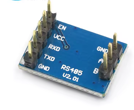
Pinout & Interface Guide
The MAX3485 module provides two distinct interfaces: the TTL side (connecting to your microcontroller) and the RS485 bus side (connecting to the network).
TTL Side (Microcontroller Interface)
Note: For standard half-duplex operation, RE and DE are often shorted together and controlled by a single MCU pin .
RS485 Bus Side (Network Interface)
Network Rules:
-
Connect the A terminals of all modules together and the B terminals together.
-
A logic “1” is transmitted when A > B (by at least 200mV); a logic “0” when A < B .
-
For long cable runs, terminate the bus with a 120Ω resistor across A and B at the two farthest ends of the cable to prevent signal reflections .
Usage Guide
Wiring Instructions
IMPORTANT: Ensure all devices on the RS485 bus share a common ground reference for reliable operation.
Standard Half-Duplex Network Setup (Arduino/ESP32)
-
Connect Power: Provide a stable +3.3V DC supply from your microcontroller to the VCC and GND pins .
-
Connect to Microcontroller:
-
Link RO to your MCU’s RX pin.
-
Link DI to your MCU’s TX pin.
-
Use a jumper wire to short the RE and DE pins together. Connect this node to a free GPIO pin (e.g., Pin 2). This single pin will control the direction of communication .
-
Connect to RS485 Bus:
-
Connect the A terminal of all modules together.
-
Connect the B terminal of all modules together.
-
For long runs, place a 120Ω resistor across the A and B terminals at the two farthest ends of the cable .
Direction Control Logic (Half-Duplex)
Since the MAX3485 operates in half-duplex mode (it cannot transmit and receive simultaneously on a 2-wire bus), you must manually control the RE/DE pin to switch between transmission and reception :
Arduino Example Code (Receive Mode)
This simple sketch demonstrates how to configure the module to listen for incoming RS485 data. It sets the RE/DE pins to receive mode, and when data is available, it prints it to the Serial Monitor.
#define RS485_CTRL 2
void setup() {
Serial.begin(115200);
Serial1.begin(9600);
pinMode(RS485_CTRL, OUTPUT);
digitalWrite(RS485_CTRL, LOW);
}
void loop() {
if (Serial1.available()) {
char c = Serial1.read();
Serial.print(c);
}
}
ESP32/ESP8266 Example Code
#define RS485_CTRL 2
void setup() {
Serial.begin(115200);
Serial2.begin(9600, SERIAL_8N1, 16, 17);
pinMode(RS485_CTRL, OUTPUT);
digitalWrite(RS485_CTRL, LOW);
}
void loop() {
digitalWrite(RS485_CTRL, LOW);
if (Serial2.available()) {
Serial.write(Serial2.read());
}
digitalWrite(RS485_CTRL, HIGH);
Serial2.print("Hello\n");
delay(1000);
}
Fail-Safe Biasing (For True Idle Bus Detection)
The MAX3485 datasheet guarantees a logic-high output only when both A and B pins are open circuit, not when the bus is idle but terminated . For robust idle bus detection in industrial environments, add external biasing resistors to force a >200mV differential on the bus when no driver is active :
Q: What is the difference between MAX3485 and MAX485?
The primary difference is the operating voltage. The MAX3485 is designed for 3.3V systems, while the MAX485 operates at 5V . Internally, they have the same pinout and functional operation. If you are using a 5V Arduino, you can use a MAX485; for 3.3V systems like ESP32, Raspberry Pi, or STM32, the MAX3485 is the correct choice .
Q: How far can I run RS485 communication?
RS485 is designed for long distances. You can reliably run cable up to 1,200 meters (approximately 4,000 feet) , particularly at lower baud rates like 9600bps . The maximum distance decreases as the data rate increases.
Q: How many devices can I connect to a single RS485 bus?
The standard MAX3485 receiver input impedance supports up to 32 transceivers on a single multi-drop RS485 network . For larger networks, you can use “1/8th unit load” transceivers (e.g., MAX3488) which allow up to 256 nodes.
Q: Is the MAX3485 compatible with 5V systems?
Yes, with proper configuration. While the MAX3485 requires a 3.3V supply for its internal circuitry, its I/O pins (RO, DI, RE, DE) are +5V logic compatible, meaning they can safely interface with a 5V microcontroller without damage . Logic “HIGH” levels above 2.0V are recognized correctly .
Q: Do I need termination resistors for my RS485 network?
Yes, for reliable long-distance or high-speed communication (typically over 100m or above 1Mbps). Place a 120Ω resistor across the A and B terminals at the two most distant nodes on the bus. This matches the cable’s characteristic impedance and prevents signal reflections that can corrupt data .
Q: Can I drive a 24V or 36V RS485 bus with this 3.3V module?
Yes. The RS485 bus operates with differential voltage swings (typically ±1.5V to ±5V), not high voltage. The MAX3485’s common-mode input range of -7V to +12V ensures it can safely interface with standard RS485 networks . However, the module should never be directly connected to 24V or 36V power lines.
Q: Why can't I get any data to transmit or receive?
The most common issue is forgetting to control the RE/DE pins. The MAX3485 must be manually told when to listen and when to talk. Ensure your code is correctly setting the RE/DEShared pin:
-
HIGH for transmit (talk)
-
LOW for receive (listen)
Q: My data is garbled or there are errors. What is wrong?
Check the following:
-
Termination: Are the 120Ω termination resistors installed at the ends of long cable runs?
-
Baud Rate: Ensure all devices on the bus (Master, Slave, Serial Monitor) are configured for the exact same baud rate.
-
Wiring: The A and B lines can be swapped. Try swapping the A and B wires on one device .
-
Fail-Safe Biasing: If the bus is idle but no nodes are transmitting, add external pull-up/pull-down resistors as described above .
Q: Why is the RO (receiver output) signal amplitude only 500mV instead of 3.3V?
This usually indicates a firmware issue. As noted in a debugging thread, the microcontroller pin connected to RO may be accidentally configured as an output (especially a digital output low), pulling the signal down. Verify your MCU code to ensure the RX pin is set as an input .
Q: What causes the bus to lock up or stop working?
If a device fails (e.g., a driver gets “stuck” in the on state), it can hold the bus lines in a dominant state, blocking all other devices. This may be caused by software (the RE/DE pin left transmitting after a crash) or hardware (a failed transceiver). Isolate the bus by disconnecting nodes one by one to identify the faulty node.
Q: What is the MAX3485 module used for?
It is used to convert UART signals to RS485 levels, allowing 3.3V microcontrollers to communicate over long distances or in noisy environments. Common applications include:
-
Reading industrial energy meters (Modbus RTU)
-
Programming industrial PLCs
-
Controlling DMX512 stage lighting
-
Multi-point sensor networks in factories
-
Building automation systems (HVAC, access control)
Q: What is the difference between half-duplex and full-duplex versions?
The MAX3485 is a half-duplex transceiver – it uses two wires for both transmitting and receiving data (time-shared). The MAX3488/MAX3491 are full-duplex versions – they use four wires (two for transmit, two for receive) allowing simultaneous bi-directional communication .
Q: What is the ESD protection rating of the MAX3485E module?
The MAX3485E variant provides ±15kV ESD protection on RS485 I/O pins (Human Body Model), ±8kV contact discharge (IEC 1000-4-2), and ±15kV air discharge (IEC 1000-4-2), making it suitable for industrial environments where ESD events are common .