Product Overview
The TP4056 1A Lipo Battery Charging Board is a complete, low-cost charging solution designed for single-cell lithium-ion and lithium-polymer (LiPo) batteries. Based on the industry-standard TP4056 chip from Top Power ASIC, this module provides a simple, safe, and efficient way to charge 3.7V rechargeable batteries using a standard Mini USB port or direct 5V power supply .
This compact module implements a Constant Current / Constant Voltage (CC/CV) charging algorithm, which is the correct method for safely charging lithium batteries. It automatically delivers the maximum preset current (1A by default) until the battery reaches 4.2V, then switches to constant voltage mode, gradually reducing the current until the battery is fully charged .
What makes this module particularly valuable for DIY projects is its simplicity: no external components are required, and the onboard LEDs provide clear visual feedback of the charging status. The red LED indicates charging is in progress, while the green LED lights up when the battery is fully charged .
Whether you are building portable electronics, powering an Arduino project with a battery backup, maintaining 18650 cells, or creating custom power banks, the TP4056 module offers a reliable, ready-to-use charging solution.
Key Features
-
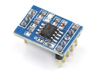
Built-in Protection Circuit: Many versions include DW01 battery protection IC and FS8205 dual MOSFETs, providing overcharge, over-discharge, overcurrent, and short-circuit protection .
-
1A Maximum Charge Current: Default charge current of 1000mA (1A), fully adjustable by changing the programming resistor (RPROG) for lower current applications .
-
CC/CV Charging Algorithm: Implements proper Constant Current / Constant Voltage charging method essential for lithium battery safety and longevity .
-
Mini USB Input: Onboard Mini-USB connector for easy connection to any standard USB charger, power bank, or computer USB port .
-
Dual-Color Status Indicator: Red LED indicates charging in progress; Green LED indicates fully charged or no battery connected .
-
Automatic Power Path Management: Supports charging while simultaneously powering a load (output terminals remain active during charging) .
-
Preset 4.2V Charge Voltage: ±1% accuracy ensures battery is charged to the correct full voltage without risk of overcharging .
-
Automatic Recharge: When a fully charged battery drops below 4.05V (approximately 80-90% capacity), a new charging cycle automatically begins .
-
Thermal Regulation: Automatically reduces charge current if internal die temperature exceeds safe limits, protecting the chip during high-current charging .
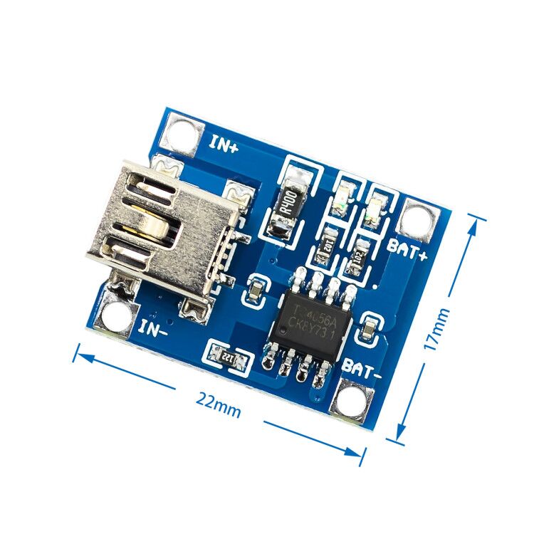
Technical Specifications
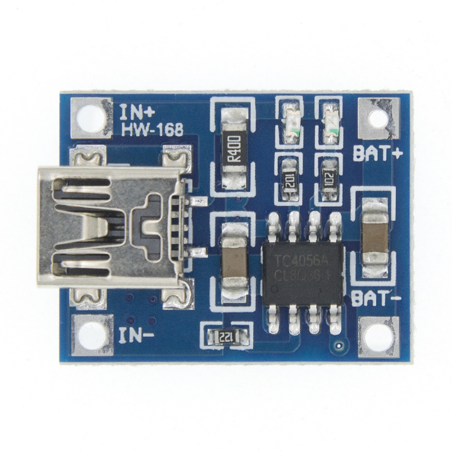
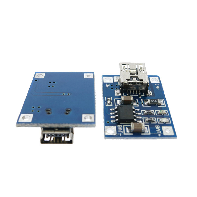
Pinout & Interface Guide
The TP4056 board is clearly labeled with connection points:
Input Side (Power Source)
Battery Connection (Charging Output)
Load Connection (Protected Output)
Status LEDs
Alternating LED behavior: When no battery is connected, the red LED may flash at 1-4Hz intervals while the green LED stays on .
Usage Guide
Basic Wiring Instructions
IMPORTANT: Always check battery polarity before connecting. Reverse polarity may damage the module.
-
Connect Power Input: Plug a standard Mini-USB cable into the board’s USB port and connect it to a 5V USB charger (capable of at least 1A output). Alternatively, connect a 5V DC supply to the IN+ and IN- pads .
-
Connect Battery: Connect the positive terminal of your 3.7V Li-ion or LiPo battery to the B+ pad. Connect the negative terminal to the B- pad. The wires should be soldered securely .
-
Observe LEDs: When charging begins, the red LED (CHRG) will turn on. When the battery reaches 4.2V and charging completes, the green LED (STDBY) will turn on, and the red LED will turn off .
-
Connect Load (Optional): For devices requiring protection from battery over-discharge, connect your load to the OUT+ and OUT- terminals. The protection circuit will cut off output if the battery voltage drops below approximately 2.4V .
Setting the Charge Current
The default charge current on most modules is 1A (1000mA). This can be adjusted for smaller batteries:
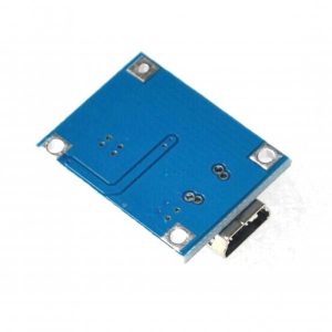
To change the current, replace the resistor connected to pin 2 (PROG) of the TP4056 IC, located on the back of the board .
Important Usage Notes
Charge Time Calculation: For a fully discharged 2000mAh battery, charging at 1A will take approximately 2 to 2.5 hours.
Input Source Requirement: For reliable 1A charging, use a USB power supply rated for at least 1A. Using a lower-current supply (e.g., a 500mA computer USB port) may cause the supply voltage to drop, reducing the charge current .
Charging While Powering a Load: When a load is connected to OUT+/OUT-, the battery continues charging through the protection circuit. If the load draws current, charging will take longer, and the green “full” LED may not illuminate because the battery never reaches the full float voltage.
Sleep Mode (Under-Voltage Lockout): When input voltage drops below approximately 3.7V, the TP4056 enters shutdown mode, consuming only leakage current from the battery to prevent deep discharge .
Q: What types of batteries can I charge with this module?
This module is designed specifically for single-cell (1S) 3.7V lithium-ion and lithium-polymer (LiPo) batteries. This includes common form factors like 18650, 14500, 16340, and pouch cells. It does NOT support 3.2V LiFePO4 batteries, multiple cells in series (2S, 3S, etc.), or NiMH/NiCd batteries .
Q: What is the difference between bare B+/B- terminals and OUT+/OUT- terminals?
The B+ / B- terminals connect directly to the battery and are always active during charging. The OUT+ / OUT- terminals pass through the DW01 protection circuit, which disconnects the load if the battery voltage drops too low (over-discharge protection) or if current exceeds safe limits. For most applications, connecting your load to OUT+/OUT- is safer .
Q: Can I use this module while it is charging the battery?
Yes. You can power your device from the OUT+/OUT- terminals while the battery is charging. The protection circuit allows simultaneous charging and discharging. However, the charging time will be longer because some current is being consumed by your load .
Q: What happens when both red and green LEDs are on simultaneously or flashing?
The red and green LEDs should never be on simultaneously during normal operation. If both are on or the red LED flashes, it may indicate:
-
No battery connected (green on, red flashing 1-4Hz)
-
Battery connection problem (poor solder joint)
-
Battery voltage is too low (below 2.9V, module may be in trickle charge mode)
Q: Why is my battery not reaching 4.2V or charging very slowly?
Check the following:
-
Input power: Ensure your USB power supply can deliver at least 1A. A weak supply will reduce the charge current
-
Battery health: Old or damaged batteries may not reach full voltage
-
Connections: Poor solder joints can create resistance, reducing effective charge current
Q: Is reverse polarity protection included?
Generally, NO. Most TP4056 modules do not include reverse polarity protection. Connecting the battery backward will likely destroy the TP4056 chip, damage the protection circuit, or cause the module to overheat. Always double-check polarity before connecting .
Q: Can I charge multiple batteries in parallel with one module?
Yes, but with caution. You can connect multiple identical 3.7V batteries in parallel (positive to positive, negative to negative) to charge them simultaneously. The charge current will be shared among the batteries, so charging will take proportionally longer. All batteries should be at similar voltage before connecting, and they should have the same capacity and chemistry .
Q: How do I change the charging current from 1A to a lower value?
The charge current is set by the resistor (RPROG) connected to pin 2 of the TP4056 chip. Replace this resistor with a higher value to reduce current. Refer to the resistor table in the “Setting the Charge Current” section .
Q: Can I use a 12V power supply as input?
No. The maximum input voltage is 5.5V DC. Applying 12V will destroy the TP4056 chip. Use a 5V USB charger or a 5V regulator (e.g., LM7805) if you only have a higher voltage supply available
Q: The module gets very hot during charging. Is this normal?
Some warmth is normal due to the linear charging method—excess voltage (5V input – 4.2V battery) is dissipated as heat. For 1A charging, power dissipation is approximately 0.8W, which will make the chip warm. The TP4056 has built-in thermal regulation that reduces current if the temperature exceeds safe limits .
Q: Why does the green LED stay on but the battery is not full?
If a load is connected to OUT+/OUT-, the load may be drawing current, preventing the battery from reaching the full 4.2V termination voltage. The circuit provides power to the load while charging, but the green LED may not illuminate until the charging current drops below the termination threshold (typically 1/10 of the programmed current) .
Q: What can I build with the TP4056 charging module?
Popular applications include:
-
18650 battery chargers for DIY power banks
-
Solar-powered lighting systems (with appropriate solar panel and regulation)
-
Arduino/ESP32 portable power supplies with battery backup
-
DIY Bluetooth speakers with rechargeable batteries
-
Smart home sensors running on battery power
-
Rechargeable LED flashlights and lanterns
Q: Can I connect a protection circuit to this module if it doesn't have one?
Many TP4056 boards already include the DW01 protection chip. Check your board visually for an 8-pin chip labeled “DW01” next to the TP4056. If your board lacks protection, you can purchase a separate DW01-based protection board and connect it in series with the battery. The protection board should go between the battery and the TP4056 module .