Product Overview
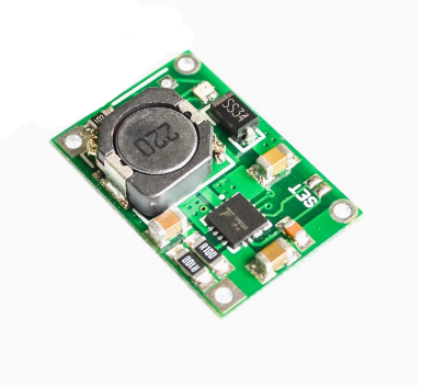
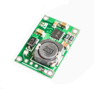
The TP5100 4.2V / 8.4V Lithium Battery Charge Management Board is a high-performance, switch-mode step-down charger for single-cell (4.2V) and dual-cell (8.4V) lithium batteries. Based on the TP5100 chip from Nanjing Top Power ASIC, this board is capable of delivering a maximum charging current of 2A, making it much faster than common TP4056 chargers .
Unlike simpler linear charger modules, the TP5100 uses a 400kHz switching regulator design . This switch-mode topology offers two major advantages: significantly less heat generation during fast 2A charging and support for a much higher input voltage range of 5V to 18V . The built-in power MOSFETs also remove the need for external Schottky diodes for reverse current protection .
The board integrates all necessary charging stages: trickle current pre-charge for deeply depleted batteries, constant current (CC) for rapid charging, and constant voltage (CV) for precise topping, ensuring battery longevity and safety . LED indicators provide clear status readout—red for charging, blue for full or no battery installed .
This module is widely used in high-capacity portable devices, power tools, and DIY battery pack (e.g., 2×18650) recharging projects where thermal efficiency and charging speed are critical. It also features full protection circuits to safeguard your batteries and the charger against overloads, shorts, and reverse connection .
Key Features
-
Compatible with Two Battery Types: Jumper-selectable operation directly on the board. Supports Single Cell (4.2V) and Dual Cell (8.4V) Lithium Ion/Polymer battery packs .
-
High Current & Switch-Mode Efficiency: Supports up to 2A charging current. The switch-mode regulator operates at 400kHz, delivering high current with minimum heat generation compared to linear chargers .
-
Wide Input Voltage Range: Operates from 5V to 18V DC input, allowing it to be powered by standard USB chargers, 9V adapters, or 12V car power sources .
-
Complete Protection Features: Equipped with input overcurrent, undervoltage lockout, chip over-temperature, short circuit, and critically, battery reverse polarity protection .
-
Smart Charging Management: Implements the full 3-stage charging process: Trickle pre-charge, Constant Current (CC) fast charge, and Constant Voltage (CV) top-off .
-
LED Status Indicators: Provides direct visual status with a Red LED (Charging) and a Blue LED (Charge Complete/Standby).
-
Built-in Power MOSFETs: Integrates the necessary power switching hardware, keeping the board compact and component count low .
-
Dual Output Ports: Features separate B+/B- pads for direct battery connection and OUT+/OUT- pads for load connection, giving flexible wiring options .
Technical Specifications
Pinout & Interface Guide
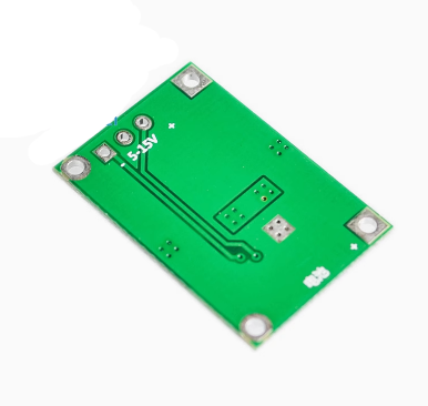
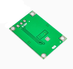
The board is clearly labeled with connection points for power, battery, and load.
Input Terminals (Power Supply)
Output Terminals (Battery & Load)
-
B+: Connect to the positive terminal (+) of the Lithium battery.
-
B-: Connect to the negative terminal (-) of the Lithium battery.
-
OUT+: Positive terminal for your load (e.g., Arduino, LEDs, Motor). This connects to the battery via the protection circuit.
-
OUT-: Negative terminal for your load .
Dual Cell Mode Switch:
On the edge of the board, there are two small gold pads labeled “Set” or a Switch .
-
Open (Default): 4.2V Mode for charging 1S Single Cell batteries (e.g., 1x 18650).
-
Short (Solder Bridge): 8.4V Mode for charging 2S Dual Cell batteries (e.g., 2x 18650 in series).
LED Indicators
Usage Guide
Wiring Instructions
Hardware Configuration:
-
Set Charging Voltage: Decide if you are charging one battery (4.2V) or two batteries in series (8.4V).
-
Connect Input Power: Connect a 5V-12V DC power supply to the VIN+ and VIN- wires/pads.
-
Connect Battery: Solder your Lithium battery(ies) to the B+ and B- pads. Ensure the polarity is correct.
-
Connect Load (Optional): If your device uses the battery for power, connect it to the OUT+ and OUT- terminals. This connection runs through the protection circuit (over-discharge cutoff).
Operating the Charger
Once the battery is connected and power is applied, the TP5100 will start the charging cycle automatically.
-
Charging: If the battery needs power, the Red LED will turn on.
-
Full: When the battery voltage reaches 4.2V (or 8.4V), the current will drop. The Red LED will turn off, and the Blue LED will turn on, signaling “Charging Complete”.
-
Maintenance: If the battery self-discharges slightly below the threshold, the charger will automatically re-start the cycle (auto-recharge) .
Current Adjustment (Optional)
The default configuration is set for approximately 2A charging. If you need to lower the current (e.g., for smaller 14500 batteries), you must replace the programming resistor (Rprog) on the board. Refer to the chip datasheet for specific resistor values for currents between 0.1A and 2A .
Q: Why should I choose TP5100 over the popular TP4056 charger?
The TP4056 is linear, restricting it to 1A charging which generates significant heat at 5V input. The TP5100 is a switching charger supporting up to 2A, producing much less heat; it also supports 5V-18V input and dual cell (8.4V) charging—capabilities the TP4056 lacks .
Q: Can I use a 12V power supply as input?
Yes. The module accepts a wide 5V-18V input, so a standard 12V adapter works perfectly. However, ensure your power source can deliver at least the current you set the charger to (e.g., 2A for full-speed charging) .
Q: What is the difference between B+/B- and OUT+/OUT-?
B+ and B- connect directly to your battery. OUT+ and OUT- are for connecting your load (the device you want to power). The OUT terminals provide output through the board’s protection circuit, which will cut off power if the battery gets too low (preventing over-discharge) .
Q: Does this module have reverse polarity protection?
Yes, the TP5100 chip specifically features battery reverse protection. If you accidentally connect the battery backward, the protection circuitry will activate to prevent damage .
Q: How do I switch between 4.2V (Single Cell) and 8.4V (Dual Cell) mode?
On the edge of the module, there are two small gold pads often labeled “Set”. If these pads are open, the module is in 4.2V (Single Cell) mode. To enable 8.4V charging for two batteries in series, you must bridge these pads with a small solder blob .
Q: The Red LED is flashing or the Blue LED is on but the battery isn't charging.
-
Blue LED On, No battery: This is normal operation. The blue LED will stay on when there is no battery connected to indicate ready state.
-
Red LED Flashing: This usually indicates an input voltage issue or a faulty connection. Check your power supply is within 5V-18V range and that the battery leads are soldered securely (no loose wires) .
Q: What happens if I try to charge a 2S (8.4V) battery in 4.2V mode?
The charger will think the battery is overcharged and will not start the charging cycle. You must physically short the “Set” pads to switch the module to 8.4V mode before connecting a dual-cell pack.
Q: Why is the output voltage (OUT+) reading 0V even when the battery is charged?
The OUT+ terminal may disable due to over-discharge protection. Simply plugging the charger in (applying VIN power) usually “wakes up” the protection circuit and re-enables the output. This is a common reset behavior for these modules .