Product Overview
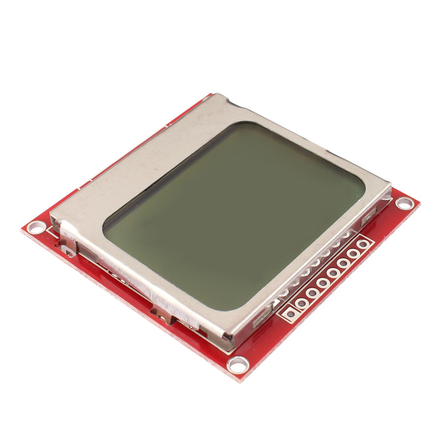
The Nokia 5110 LCD Shield Module is a compact, low-power graphical display module that brings classic mobile phone screen technology to your electronics projects. Featuring an 84×48 pixel resolution and a vibrant blue backlight, this display is perfect for Arduino, Raspberry Pi, ESP32, and other microcontroller projects requiring clear visual feedback without consuming excessive power or I/O pins .
Originally designed as a replacement screen for the Nokia 5110 mobile phone, this LCD module utilizes the PCD8544 controller chip—the same driver found in the Nokia 3310 LCD . This controller provides all necessary functions for driving a graphic display of 48 rows and 84 columns, including on-chip generation of LCD supply and bias voltages, resulting in minimal external components and ultra-low power consumption .
The module communicates via a serial bus interface (SPI), requiring only 5-6 I/O pins to operate . This makes it ideal for projects where I/O pins are limited. The blue backlight ensures excellent readability even in dim lighting conditions, while the high-contrast LCD provides crisp text and graphics display .
Whether you’re building a weather station, a sensor data monitor, a handheld game console, or a system status dashboard, this Nokia 5110 LCD module offers an affordable, reliable, and easy-to-integrate display solution .
Key Features
-
84×48 Pixel Resolution: Clear display of text, custom graphics, icons, and simple animations with 84 columns by 48 rows of pixels
-
Blue Backlight: Vibrant blue backlight for enhanced visibility in various lighting conditions; backlight can be controlled via GPIO to conserve power
-
Low Power Consumption: Operating current typically below 200μA with power-down mode support, making it ideal for battery-powered projects
-
SPI Serial Interface: Communicates via standard SPI protocol (SCLK, MOSI, DC, CE, RST), requiring minimal I/O pins (typically 5-6 pins)
-
PCD8544 Controller: Industry-standard LCD controller with on-chip generation of LCD supply and bias voltages
-
Adjustable Contrast: Software-controlled contrast levels to optimize display clarity under different conditions
-
Compact Form Factor: Small PCB footprint (approx. 45mm x 45mm) for easy integration into space-constrained projects
-
Wide Compatibility: Works with Arduino, Raspberry Pi, ESP8266, ESP32, STM32, and other 3.3V/5V logic systems
-
Mounting Holes: Pre-drilled mounting holes for secure attachment to enclosures or project boxes
Technical Specifications
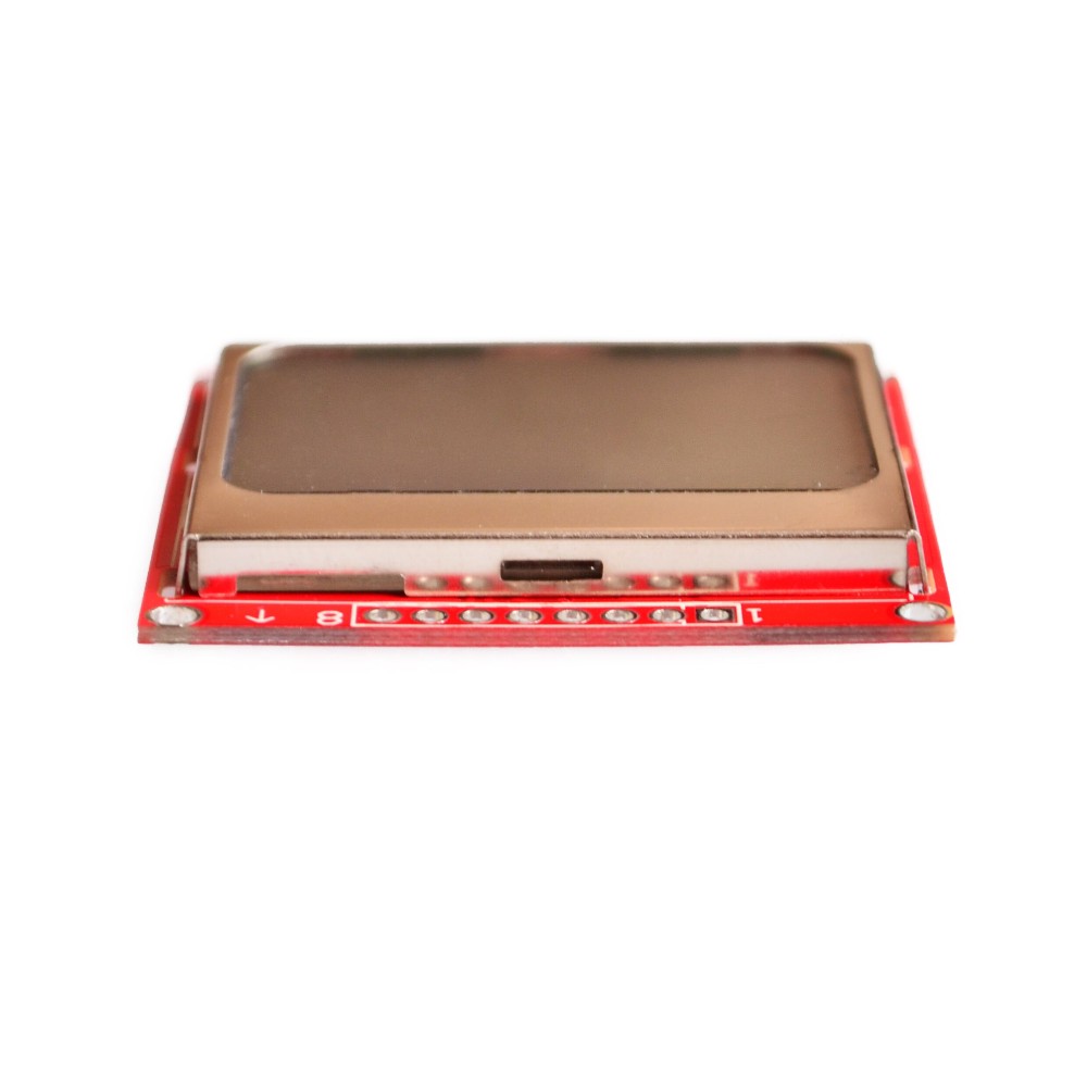
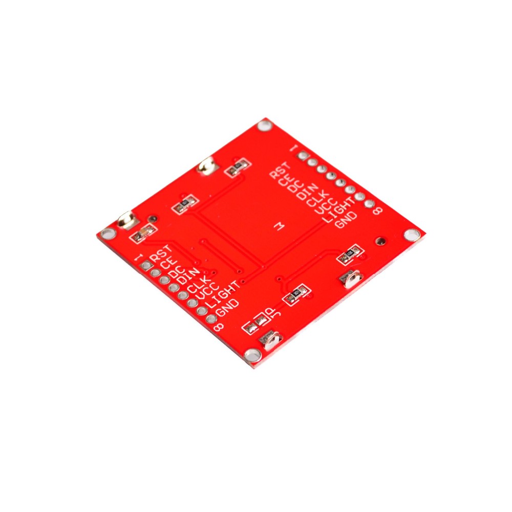
Pinout & Interface Guide
The Nokia 5110 LCD module features 8 pins for connection to your microcontroller :
Important Note: The LIGHT pin toggles the backlight. Connecting it to GND turns the backlight ON; connecting to VCC turns it OFF .
Usage Guide
Arduino Setup
Hardware Connection (Standard Wiring)
Note: For Arduino Mega users, the pin connections remain the same; the library will handle the SPI mapping automatically .
Software Installation
-
Download the LCD5110 Library:
-
Install the Library:
-
Run Example Sketch:
Basic Example Code (Arduino)
#include <SPI.h>
#include <Adafruit_GFX.h>
#include <Adafruit_PCD8544.h>
Adafruit_PCD8544 display = Adafruit_PCD8544(8, 9, 10, 11, 12);
void setup() {
display.begin();
display.setContrast(50);
display.clearDisplay();
display.setTextSize(1);
display.setTextColor(BLACK);
display.setCursor(0, 0);
display.println("Nokia 5110");
display.println("84x48 Display");
display.println("Hello World!");
display.display();
}
void loop() {
}
Raspberry Pi Setup
Hardware Connection (SPI Mode)
Important: The Nokia 5110 LCD operates at 3.3V logic. For Raspberry Pi, connect VCC to 3.3V (Pin 1) only .
Enable SPI on Raspberry Pi
-
Run sudo raspi-config
-
Navigate to Interface Options → SPI → Yes to enable
-
Reboot your Raspberry Pi
Install Required Libraries
cd ~
git clone git://git.drogon.net/wiringPi
cd wiringPi
./build
pip install spidev
Python Example Code
import spidev
import RPi.GPIO as GPIO
import time
RST_PIN = 25
DC_PIN = 24
CE_PIN = 23
GPIO.setmode(GPIO.BCM)
GPIO.setup(RST_PIN, GPIO.OUT)
GPIO.setup(DC_PIN, GPIO.OUT)
GPIO.setup(CE_PIN, GPIO.OUT)
spi = spidev.SpiDev()
spi.open(0, 0)
spi.max_speed_hz = 4000000
spi.mode = 0
GPIO.output(RST_PIN, GPIO.LOW)
time.sleep(0.001)
GPIO.output(RST_PIN, GPIO.HIGH)
Adjusting Display Contrast
The display contrast can be adjusted in software to optimize readability for your specific lighting conditions. In the Arduino library, use display.setContrast(value) where value ranges from 0 to 100 .
For Raspberry Pi, the contrast can be modified in the source code by changing the contrast variable (typical default is 45). If the display appears too dark, decrease the value; if too light, increase the value .
Important Usage Notes
-
Power Supply: The display works with both 3.3V and 5V logic, but for best results with Raspberry Pi, use 3.3V .
-
Backlight Control: The backlight can be turned on/off via software by connecting the LIGHT pin to a GPIO pin and controlling it programmatically, helping conserve power in battery-operated projects .
-
Contrast Adjustment: Different modules may have different optimal contrast settings. Start with a mid-range value (45-50) and adjust until the display is crisp and clear .
-
Low Power Applications: The display’s typical operating current below 200µA makes it excellent for battery-powered projects .
-
Viewing Angle: The LCD has a specific optimal viewing angle; position the display accordingly in your enclosure for best visibility.
Q: What types of microcontrollers can I use with this display?
The Nokia 5110 LCD module is compatible with Arduino, Raspberry Pi, ESP32, ESP8266, STM32, PIC, AVR, and most other 3.3V/5V microcontrollers .
Q: Can I display graphics and custom characters on this screen?
Yes. With 84×48 pixel resolution, you can display text, custom graphics, icons, simple animations, and even bitmap images. The PCD8544 controller allows pixel-level control
Q: Is the backlight color only blue?
This specific module features a blue backlight. However, some variants are available with white or other color backlights. The blue backlight provides high contrast and excellent visibility
Q: How do I turn the backlight on and off?
The LIGHT pin is active low: connecting it to GND turns the backlight ON, while connecting it to VCC turns it OFF. For software control, connect the LIGHT pin to a GPIO pin and control it programmatically .
Q: What is the maximum SPI speed for this display?
The module supports data transfer rates up to 4 Mbps, allowing fast screen updates without waiting times .
Q: Can I power this display from a 5V Arduino?
Yes. The display accepts both 3.3V and 5V power. When using 5V power, ensure your signal pins are at 3.3V logic or use voltage dividers/level shifters for reliable communication .
Q: Why doesn't my display show anything or shows garbled content?
Common causes include:
-
Loose or incorrect wiring connections
-
Missing or incorrect library installation
-
Wrong pin assignments in code
-
Insufficient power (ensure VCC and GND are properly connected)
-
Contrast setting too high or too low
Q: How do I fix the display if everything appears too dark or too light?
Adjust the contrast setting in your software. For Arduino, use display.setContrast(value). For Raspberry Pi, modify the contrast variable in the source code. Try values between 30 and 90, with 45 as a good starting point .
Q: Can I use this module with Raspberry Pi's 5V pins?
No. The Nokia 5110 LCD uses 3.3V logic. Connect VCC to 3.3V (Pin 1) on the Raspberry Pi. Using 5V may damage the display .
Q: What can I build with this Nokia 5110 LCD module?
Popular applications include:
-
Weather stations: Display temperature, humidity, pressure, and forecast icons
-
Sensor monitors: Real-time display of sensor readings from multiple sensors
-
System status dashboards: Show CPU/MEM usage for Raspberry Pi or other systems
-
Handheld games: Create simple gaming devices and retro game consoles
-
Data loggers: Display logged data and statistics
-
Robotics: Show robot status, sensor readings, and debug information
-
Home automation controllers: User interface for smart home systems
Q: Is this display suitable for battery-powered projects?
Yes, absolutely. With typical operating current under 200µA and power-down mode support, the Nokia 5110 LCD is an excellent choice for portable, battery-powered devices .
Q: Do I need additional components to use this display with 5V Arduino?
While the display works with 5V power, the SPI communication operates at 3.3V logic. For reliable long-term use with 5V microcontrollers, consider using logic level converters or voltage dividers on the signal lines .
Q: Where can I find more code examples and libraries?
Popular libraries include:
-
Adafruit PCD8544 (Arduino)
-
LCD5110_graph (Arduino)
-
spidev (Python for Raspberry Pi)
-
WiringPi (C++ for Raspberry Pi)