Product Overview
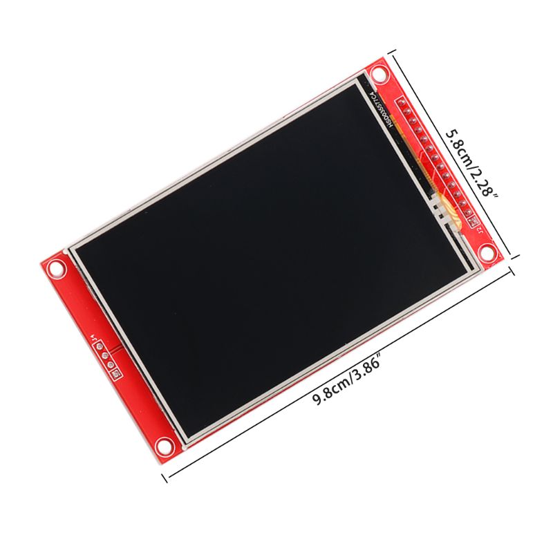
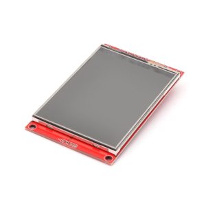
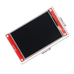
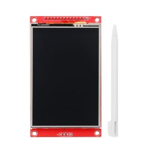
The 3.5-inch TFT Touch Display is a vibrant, full-color LCD screen designed to bring graphical user interfaces (GUIs) to your Arduino projects. Powered by the ILI9486 driver IC, this display offers a crisp 480×320 resolution . Unlike many complex TFTs that require a messy 8-bit or 16-bit parallel wiring, this model communicates via a simple 4-wire SPI interface, saving your microcontroller’s precious I/O pins for sensors and actuators .
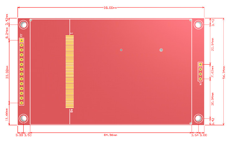
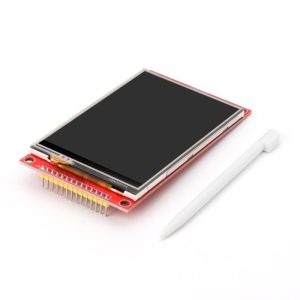
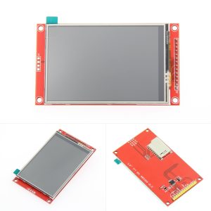
It comes as a ready-to-go shield module (with 34-pin female headers), allowing you to directly stack it onto Arduino UNO, Mega2560, or DUE boards without any soldering . The package includes a resistive touchscreen (with a stylus pen) and an onboard MicroSD card slot, making it perfect for full-fledged menu systems, data loggers, or retro gaming projects .
Key Features
-
3.5-Inch High-Resolution Display: 480×320 pixel color TFT provides rich graphic capabilities and wide viewing angles .
-
SPI Interface (4-Wire): Uses Serial Peripheral Interface for communication, significantly reducing the number of pins required compared to parallel displays .
-
Integrated Resistive Touchscreen: Includes an XPT2046 touch controller; comes with a stylus for precise menu navigation .
-
Plug-and-Play Shield Design: Directly stacks onto UNO, Mega2560, and DUE via pre-soldered female headers – no wiring required .
-
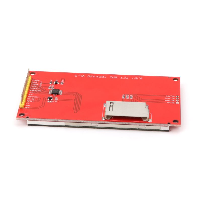
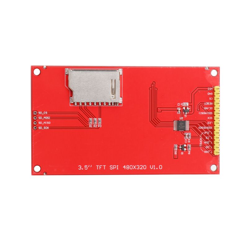
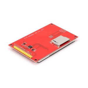
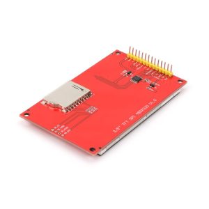
Built-in MicroSD Card Slot: Load images, fonts, and data from a standard TF/MicroSD card .
-
Level-Shifted Logic: Onboard circuit supports both 5V (Arduino UNO/Mega) and 3.3V (DUE) logic levels safely .
-
High Color Depth: Supports 18-bit color (262,000 shades) for smooth gradients and realistic images .
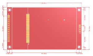
Technical Specifications
Pinout & Interface Guide
Since this is a shield, you won’t typically wire it manually; you simply attach it to the board. However, if you are using an ESP32 or wiring a universal breakout, the standard SPI pins are as follows:
Note: The SPI pins (MOSI, MISO, SCK) are fixed hardware pins on the Arduino. The shield will connect to these automatically .
Usage Guide
1. Hardware Setup (Direct Shield)
-
Alignment: Ensure the pins on the bottom of the TFT shield align perfectly with the headers on your Arduino UNO or Mega2560 .
-
Mount: Press the shield firmly onto the board. Double-check that none of the pins are bent underneath the board .
-
Power: For an Arduino UNO, simply plug in the USB cable. The shield will draw power from the 5V pin.
2. Software & Libraries
Many ILI9486 SPI screens are compatible with the Waveshare_ILI9486 library or Bodmer’s TFT_eSPI library (recommended for performance).
Steps for TFT_eSPI (Highly Recommended):
-
Install the “TFT_eSPI” library via the Arduino Library Manager.
-
Locate the User_Setup.h file:
-
Alternatively, if using the Adafruit library style: You can use the “Waveshare_ILI9486” library .
3. Running a Test
Upload the Graphicstest sketch included in the TFT_eSPI library. If you see a white screen, ensure the SPI wiring is correct and that the Chip Select (CS) pins are matching the pins defined in your library setup.
4. Utilizing the MicroSD Card
The SD card slot shares the SPI bus. To use it:
-
Insert a FAT16/FAT32 formatted card.
-
Note the unique Chip Select pin for the SD Card (often pin 4, or a dedicated pin defined in the library).
-
Initialize using standard Arduino SD library: SD.begin(4); .
Q: Is this screen compatible with the Arduino Mega 2560 or Due?
Yes. The shield is designed to be physically compatible with both UNO and MEGA 2560 boards. However, be aware that the Mega often runs TFTs slower than the UNO due to specific pin mapping .
Q: Does this screen work with Raspberry Pi or ESP32?
It uses SPI and requires 3.3V logic, making it ideal for ESP32. However, it is not plug-and-play for Raspberry Pi without specific driver configurations .
Q: What is the difference between SPI and 8-bit parallel mode?
SPI uses only 4-5 pins, which saves IO but is significantly slower for refreshing the whole screen. Parallel mode (8/16 bit) is faster but uses many pins; this specific module uses a faster SPI driver than standard software SPI.
Q: I plugged the shield in, but the screen is white!
This usually means the backlight is on but the initialization failed. Checkpoints:
-
Ensure the shield is fully seated and no pins are bent .
-
Verify you selected the correct Board in the Arduino IDE (e.g., Arduino Mega2560).
-
Make sure you are using a library that supports the ILI9486 over SPI (like TFT_eSPI).
-
Try adjusting the LCD contrast or resetting the board .
Q: How do I calibrate the resistive touch screen?
Resistive touch screens often need calibration. Use a library like XPT2046_Touchscreen. Run the calibration sketch to get the raw ADC values (min/max for X and Y axes) and plug these numbers into your main code to map them to the 480×320 screen resolution.
Q: Why is my touch screen inaccurate near the edges?
It is characteristic of resistive touch technology. Calibration is mandatory for accuracy, and using a stylus (provided) is recommended over finger presses for tight menu selections.
Q: Can I control the backlight brightness?
Yes. The backlight is powered by one or more LEDs. If you cut the jumper connecting the backlight to Vcc and connect the pad to a PWM-capable digital pin, you can use analogWrite() to dim the screen .
Q: Does the SD card work simultaneously with the screen?
Yes, but caution is required. They share the SPI bus (MOSI, MISO, SCK). You must switch the Chip Select (CS) pin LOW only for the device you wish to talk to (Screen or SD Card). Ensure you set the CS of the other device HIGH before switching.