Product Overview
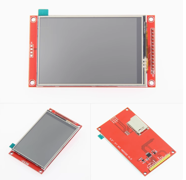
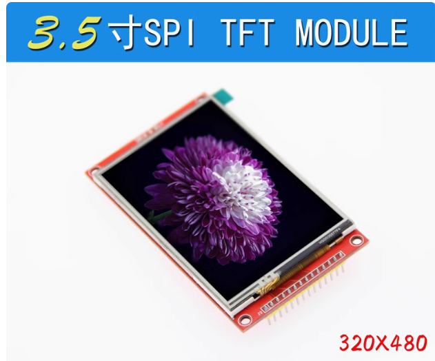
The 3.5-inch TFT Touch Display is a vibrant, high-resolution color screen designed to bring graphical user interfaces (GUIs) to your embedded projects. Powered by the ILI9488 driver IC, this display offers a crisp 480×320 pixel resolution (RGB 65K color) . Unlike complex parallel displays that consume many I/O pins, this model communicates via a simple 4-wire SPI interface, requiring as few as 4-5 I/O pins to operate .
This module comes with a resistive touchscreen (using the XPT2046 controller) and includes a stylus pen for precise interaction . An onboard MicroSD card slot is also provided, allowing you to load images, fonts, and data directly from a memory card . The module features a 14-pin 2.54mm pitch header, making it compatible with breadboards and standard female-to-female jumper wires .
Whether you are building an industrial HMI control panel, a smart home touch interface, a portable gaming console, or a data logger, this 3.5-inch display offers the perfect balance of performance and ease of use.
Key Features
-
3.5-Inch High-Resolution Display: 480×320 pixel resolution with 65K/262K color depth, providing rich graphic capabilities and wide viewing angles .
-
4-Wire SPI Interface: Uses the SPI serial bus for communication, significantly reducing pin usage compared to parallel interfaces (requires only 4-5 I/O pins) .
-
Integrated Resistive Touchscreen: Includes an XPT2046 touch controller and comes with a stylus pen for precise menu navigation and GUI interaction .
-
Built-in MicroSD Card Slot: Onboard MicroSD card slot for loading images, fonts, and data storage .
-
Wide Voltage Compatibility: Operates with 3.3V – 5V power supply, making it compatible with both 5V (Arduino UNO/Mega) and 3.3V (ESP32/STM32) logic systems .
-
High-Speed SPI Support: Supports SPI transfer rates up to 27MHz for smooth UI animations and real-time data visualization .
-
Adjustable Backlight: Dedicated LED pin allows PWM-based brightness control .
-
Flexible Pin Header: 14-pin 2.54mm pitch header, compatible with standard jumper wires and breadboards .
Technical Specifications
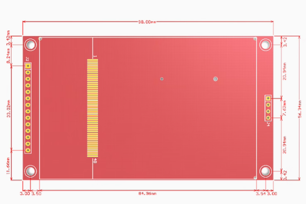
Pinout & Interface Guide
The 3.5-inch ILI9488 SPI module typically features 14 pins (2.54mm pitch) . The following pins are categorized by function for easier reference:
LCD Display Pins
Resistive Touch Pins (XPT2046)
Note: The SD card slot uses the standard SPI bus and requires a dedicated Chip Select (SD_CS) pin. Common configurations use GPIO4 or pin 4 for SD_CS .
Usage Guide
Hardware Connection
The 14-pin 2.54mm header allows easy connection using female-to-female jumper wires:
Software Setup (Arduino IDE / ESP32)
The best library for this display is TFT_eSPI by Bodmer, which provides excellent performance and supports the ILI9488 over 4-wire SPI.
1. Install Required Libraries
2. Configure TFT_eSPI (User_Setup.h)
After installing the library, navigate to the TFT_eSPI folder and edit the User_Setup.h file .
Uncomment or add the following configuration:
#define ILI9488_DRIVER
#define TFT_WIDTH 320
#define TFT_HEIGHT 480
#define TFT_MISO 19
#define TFT_MOSI 23
#define TFT_SCLK 18
#define TFT_CS 15
#define TFT_DC 2
#define TFT_RST 4
#define TOUCH_CS 21
#define SPI_FREQUENCY 27000000
3. Initialization Example Code
#include <SPI.h>
#include <TFT_eSPI.h>
TFT_eSPI tft = TFT_eSPI();
void setup() {
Serial.begin(115200);
tft.init();
tft.setRotation(1);
tft.fillScreen(TFT_BLACK);
tft.setTextColor(TFT_WHITE, TFT_BLACK);
tft.setTextSize(2);
tft.drawString("Hello, ILI9488!", 50, 200);
}
void loop() {
}
Important Notes
-
SPI Bus Sharing: The display, touch controller, and MicroSD card all share the same SPI bus (MOSI, MISO, SCK). Each device requires a unique CS (Chip Select) pin .
-
Touch Calibration: For resistive touch screens, calibration is mandatory for accuracy. Run a calibration sketch to get the raw ADC values (min/max for X/Y axes) and map them to the 480×320 screen resolution .
-
Backlight Control: The LED pin can be controlled by PWM to adjust brightness. Connect to a PWM-capable pin and use analogWrite() .
Q: What is the advantage of SPI over parallel displays?
SPI uses only 4-5 I/O pins, saving your microcontroller’s precious pins for other functions like sensors and actuators. This makes them much easier to wire and integrate .
Q: Is this screen compatible with Arduino Uno, Mega, ESP32, or STM32?
Yes. The module works with all these boards. For 5V boards (Arduino Uno/Mega), the logic is 5V tolerant; for 3.3V boards (ESP32/STM32), connect VCC to 3.3V .
Q: What is the difference between ILI9486 and ILI9488?
The ILI9488 is the newer, improved version of the ILI9486, offering better performance and display quality . The primary functional difference is interface support: the ILI9486 natively supports SPI while the ILI9488 supports both 16-bit parallel and SPI interfaces .
Q: I wired everything correctly, but the screen is white/blank!
This typically indicates the display is powered but not initialized:
-
Ensure the correct driver (#define ILI9488_DRIVER) is selected in User_Setup.h .
-
Verify all wiring connections, especially VCC, GND, MOSI, SCK, and CS.
-
Check the SPI frequency setting (try lowering it to 16MHz if unstable).
-
Ensure the RESET pin is correctly connected and toggled.
Q: The touch screen is not responding or inaccurate.
Resistive touch requires calibration:
-
Ensure TOUCH_CS is defined in User_Setup.h .
-
Run a calibration sketch to get the min/max ADC values for X/Y axes.
-
Map the raw ADC values to the 480×320 screen resolution .
Q: The SD card and touch screen are both not working together.
This is a common SPI bus conflict. Ensure each device has a unique CS (Chip Select) pin and that only one device is selected at a time. Check that your code de-asserts (sets HIGH) the CS of the other device before communicating with the one you need.
Q: Why are the touch coordinates reversed?
You may need to swap X/Y or invert one axis in your code. In the TFT_eSPI User_Setup.h, you can adjust TOUCH_ORIENTATION to correct axis swapping and inversion.
Q: What can I build with this 3.5-inch touch display?
Popular applications include:
-
Industrial HMI/HMI: Touch control panels for machinery and automation
-
Smart Home Control Panels: Central touch interface for lights, HVAC, and security
-
Portable Gaming Devices: Retro game emulators and handheld consoles
-
Data Loggers: Visualizing sensor data (temperature, humidity) graphically
-
Desktop Event Notifiers: Display system alerts and notifications
Q: Where can I find more code examples and libraries?
The best resources are:
-
TFT_eSPI Library: The most popular Arduino library for ILI9488 displays
-
GitHub: “Bodmer/TFT_eSPI” for extensive examples and documentation
-
Adafruit ILI9341: The ILI9488 is command-compatible with the ILI9341 family