Product Overview
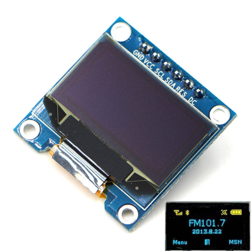
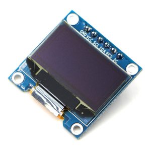
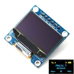
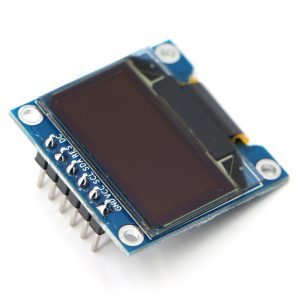
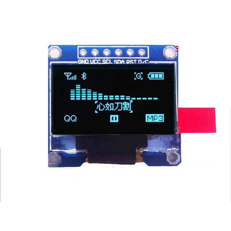
The 0.96-inch Yellow+Blue 6-Pin SPI OLED Display is a compact, high-contrast dual-color graphic display module that brings vibrant visual feedback to your electronics projects. Powered by the SSD1306 driver IC, this display features a striking fixed dual-color layout—yellow on the top portion and sky blue on the bottom—with a crisp 128×64 pixel resolution.
Unlike traditional LCDs that require a power-consuming backlight, OLED technology allows each pixel to emit its own light. This self-emissive design provides true blacks (inactive pixels are completely off), an exceptional 10,000:1 contrast ratio, and >160° viewing angles. The result is a professional-looking display where text and graphics appear to “float” on a pure black background—all while consuming minimal power.
This module uses the SPI (Serial Peripheral Interface) protocol, which requires 6 pins for communication. The 6-pin interface provides faster data transfer compared to the 4-pin I2C version, making SPI ideal for applications that require smooth animations, frequent screen updates, or large amounts of displayed data.
With support for both 3.3V and 5V logic (operating range 2.8V–5.2V), this module is directly compatible with Arduino, ESP32, ESP8266, Raspberry Pi, STM32, and most other development boards—no level shifters required. The ultra-low power consumption (approximately 0.04W–0.06W during normal operation) makes this display ideal for battery-powered IoT devices, wearable projects, smart home interfaces, data loggers, and portable instruments.
Color Note: This display is monochrome per pixel. Individual pixels are either ON or OFF, but the OLED panel is physically manufactured with two distinct materials: the top portion emits yellow light, while the bottom portion emits sky blue light. You cannot change individual pixel colors through software—the color is determined by the pixel’s vertical position on the screen.
Key Features
-
128×64 Pixel Resolution: High-definition display with 128 columns and 64 rows—capable of showing detailed graphics, bitmaps, and up to 8 lines of small text
-
Yellow+Blue Dual-Color Display: Distinctive yellow top section and sky blue bottom section—ideal for creating visual hierarchy in UIs (warnings/status at top, data/content at bottom)
-
SSD1306 Driver IC: Industry-standard controller with built-in display buffer, charge pump, and extensive library support (Adafruit, U8g2, etc.)
-
SPI Interface: 6-pin SPI protocol provides faster data transfer than I2C, making it ideal for animations and frequent screen updates
-
Wide Voltage Compatibility: Accepts 3.3V–5V DC power, compatible with both 5V (Arduino) and 3.3V (ESP32/ESP8266) logic systems
-
Ultra-Low Power Consumption: Consumes approximately 0.04W–0.06W during normal operation (~15mA at 3.3V), standby current <10µA—ideal for battery-powered projects
-
Wide Viewing Angle: >160° visibility ensures clear readouts from almost any angle without contrast shift
-
Wide Operating Temperature: Rated for -30°C to +80°C, suitable for industrial and outdoor applications
-
Self-Emitting OLED Technology: No backlight required—true blacks provide exceptional contrast and superior readability in all lighting conditions
-
Compact Size: Small 27mm × 27mm × ~4mm footprint for easy integration into space-constrained projects
Technical Specifications
Pinout & Hardware Connection Guide
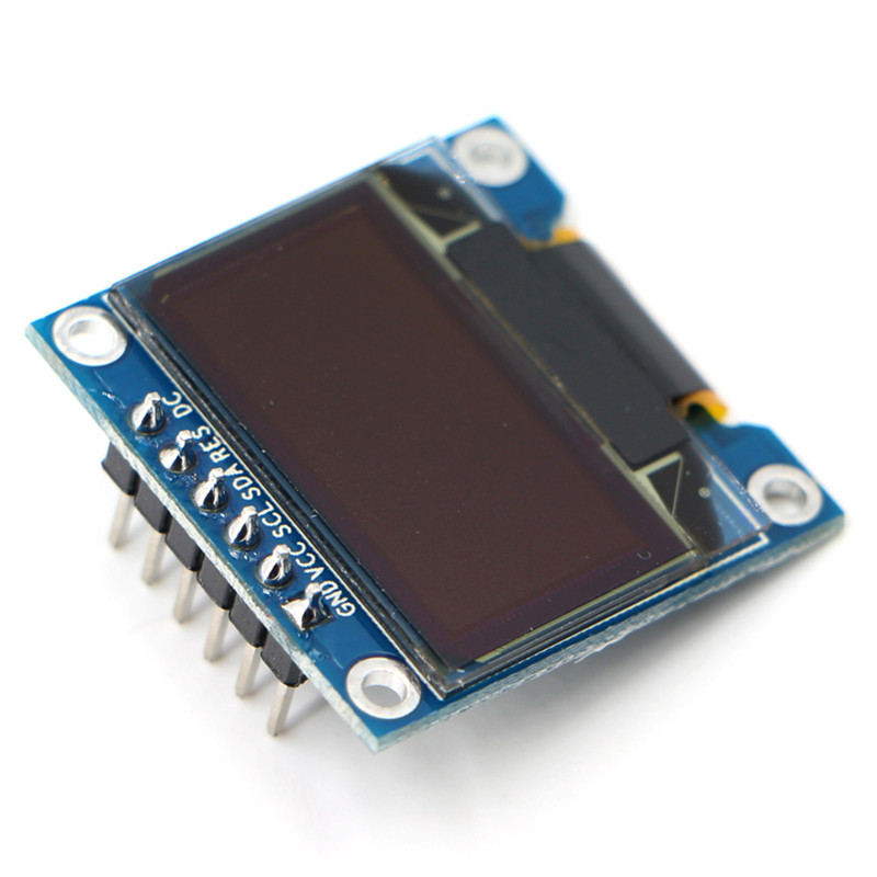
The 6-pin SPI OLED module uses the following pin configuration. Note: Pin labeling may vary slightly between manufacturers; always verify the silkscreen on your specific board.
*Some modules include a separate CS (Chip Select) pin, making them 7-pin versions. If your module has a CS pin, it is not required for basic operation with a single device but can be connected to an available GPIO.*
SPI Pin Mapping for Common Development Boards:
⚠️ Important Electrical Notes:
-
For ESP32/ESP8266: Always connect VCC to 3.3V, not 5V, as these microcontrollers are not 5V tolerant
-
For 5V microcontrollers (Arduino Uno/Mega): The display’s 3.3V logic level is recognized as a valid HIGH signal, so no level shifter is generally needed
-
I2C vs. SPI: This 6-pin module is configured for SPI communication. The 4-pin version is for I2C
Wiring Diagram (Arduino Uno):
OLED Module          →    Arduino Uno
─────────────────────────────────────
GND                  →    GND
VCC                  →    5V (or 3.3V)
SCL (SCK)            →    D13 (SCK)
SDA (MOSI)           →    D11 (MOSI)
RES (RST)            →    D12 (or D13)
DC                   →    D10
(CS)                 →    (Optional, pull to GND if not used)
Usage Guide
Software Setup (Arduino IDE)
The SSD1306 is supported by several popular libraries. Adafruit_SSD1306 (paired with Adafruit_GFX) is the most common and well-documented option for beginners. For advanced graphics and more font options, U8g2 is also a great choice.
Installing the Adafruit Libraries
-
Open Arduino IDE → Sketch → Include Library → Manage Libraries
-
Search for and install:
-
When prompted to install dependencies, click Install All
Basic Test Sketch (SPI Mode)
After installing the libraries, upload this sketch to verify your display is working:
#include <SPI.h>
#include <Adafruit_GFX.h>
#include <Adafruit_SSD1306.h>
#define SCREEN_WIDTH 128
#define SCREEN_HEIGHT 64
#define OLED_MOSI 11
#define OLED_CLK 13
#define OLED_DC 10
#define OLED_CS 12
#define OLED_RESET 9
Adafruit_SSD1306 display(SCREEN_WIDTH, SCREEN_HEIGHT,
OLED_MOSI, OLED_CLK, OLED_DC, OLED_RESET, OLED_CS);
void setup() {
Serial.begin(9600);
if(!display.begin(SSD1306_SWITCHCAPVCC, 0x3C)) {
Serial.println(F("SSD1306 allocation failed"));
for(;;);
}
display.clearDisplay();
display.setTextSize(2);
display.setTextColor(SSD1306_WHITE);
display.setCursor(20, 25);
display.println("OLED Ready!");
display.display();
}
void loop() {
}
Alternative SPI Initialization (if the above fails)
Some library versions require explicit pin definitions in the constructor. If the previous example doesn’t compile, try this approach:
#include <SPI.h>
#include <Adafruit_GFX.h>
#include <Adafruit_SSD1306.h>
#define SCREEN_WIDTH 128
#define SCREEN_HEIGHT 64
#define OLED_RESET 9
Adafruit_SSD1306 display(SCREEN_WIDTH, SCREEN_HEIGHT, &SPI, OLED_DC, OLED_CS, OLED_RESET);
Understanding the Display Buffer Workflow
The Adafruit_SSD1306 library uses a buffer-based drawing system:
-
Drawing functions (e.g., drawPixel, println, fillRect) write to an in-memory buffer
-
The screen does NOT update immediately
-
You must call display.display() to transfer the buffer contents to the actual OLED panel
This double-buffering technique prevents screen flicker and allows you to build complex frames efficiently.
Basic Graphics Functions
display.clearDisplay();
display.drawPixel(10, 10, SSD1306_WHITE);
display.drawLine(0, 0, 127, 63, SSD1306_WHITE);
display.drawRect(10, 10, 50, 30, SSD1306_WHITE);
display.fillRect(70, 10, 40, 30, SSD1306_WHITE);
display.drawCircle(64, 32, 20, SSD1306_WHITE);
display.fillCircle(64, 32, 15, SSD1306_WHITE);
display.setTextSize(1);
display.setTextColor(SSD1306_WHITE);
display.setCursor(0, 55);
display.print("Graphics Demo");
display.display();
Using U8g2 Library (Alternative)
The U8g2 library offers more fonts and advanced graphics features. Install it via the Library Manager, then use:
#include <Arduino.h>
#include <U8g2lib.h>
#include <SPI.h>
U8G2_SSD1306_128X64_NONAME_F_4W_SW_SPI u8g2(U8G2_R0, 13, 11, 12, 10, 9);
void setup() {
u8g2.begin();
u8g2.enableUTF8Print();
}
void loop() {
u8g2.firstPage();
do {
u8g2.setFont(u8g2_font_ncenB08_tr);
u8g2.drawStr(0, 20, "Hello World!");
} while ( u8g2.nextPage() );
delay(1000);
}
Power Management for Battery-Powered Projects
OLED displays are excellent for low-power applications because only lit pixels consume power. The dual-color variant’s power consumption is approximately the same as monochrome versions when displaying typical mixed content.
Power-Saving Tips:
-
For battery-powered applications, update the display only when values change rather than continuously refreshing
-
Use the display’s built-in power-down mode when not needed (send display.ssd1306_command(SSD1306_DISPLAYOFF) to turn OFF)
-
Avoid displaying large white or high-density areas continuously to maximize battery life
Color Division Notice
Please note: This display is “dual-color” only in the sense that different screen regions are physically different colors. The top section (approximately the first half of the 64 rows, typically 32–36 rows) emits yellow light, while the bottom section emits sky blue light. This color division is fixed by the OLED panel’s physical construction—you cannot change individual pixel colors or control which pixels are yellow vs. blue through software.
The SSD1306 driver treats the entire screen as monochrome (pixels are either ON or OFF), with the color determined solely by the pixel’s physical location on the screen. When planning your user interface, consider reserving the top yellow area for alerts, titles, or warnings, and the larger blue area for data values, menus, and content.
Q: What is the difference between this 6-pin SPI version and the 4-pin I2C version?
The 6-pin SPI version (this product) offers faster data transfer and is better suited for applications requiring smooth animations, frequent screen updates, or displaying large amounts of data. It requires 5-6 I/O pins. The 4-pin I2C version is simpler to wire (only 2 data lines) but slower, making it better for projects where pin availability is a constraint.
Q: How does the Yellow+Blue dual-color work? Is it a true color display?
No—it is still a monochrome display. The OLED panel is physically manufactured with two distinct materials: the top portion emits yellow light when pixels are ON, while the bottom portion emits sky blue light. You cannot change individual pixel colors through software—the color is determined solely by the pixel’s vertical position (Y coordinate) on the screen. This creates a striking two-tone effect ideal for separating UI regions (e.g., yellow status bar, blue content area).
Q: Can I change which rows are yellow vs. blue?
No. The color division is fixed at the hardware level—you cannot change it through software. If you need a fully configurable color display, consider an RGB OLED (which uses a different driver IC).
Q: How many characters can the display show?
With the default 8×8 pixel font, the display can show approximately 16 characters × 8 lines = 128 characters total. With larger fonts (e.g., 16×16 pixels), fewer characters fit—about 8 characters × 4 lines = 32 characters.
Q: What is the lifespan of the OLED display?
OLEDs have a rated lifespan of approximately 20,000–30,000 hours of continuous operation (about 2.5–3.5 years). Displaying the same static image for extremely long periods (e.g., thousands of hours) can cause “burn-in” or uneven pixel wear, which may be more noticeable on dual-color displays due to differences in material aging rates.
Q: How much current does the display draw?
Power consumption is directly related to how many and which pixels are lit:
-
All pixels off (black screen): Standby current <10µA
-
Typical text/dashboard (~25% pixels lit): ~10-15mA
-
Full screen white: ~20-25mA
Q: Why does my display stay blank after power-up?
This usually indicates one of these issues:
-
Wrong wiring – Verify VCC→5V (or 3.3V), GND→GND, SCK→D13, MOSI→D11, DC→D10, RES→D9
-
Incorrect library configuration – Ensure you are using the SPI constructor, not the I2C version
-
Missing display.display() call – Drawing functions write to a buffer; you must call display.display() to push the buffer to the screen
-
Power supply – Ensure your power source can deliver ~30mA
Q: Does this module have a Chip Select (CS) pin?
Some 6-pin modules omit the CS pin (tied to GND internally), making them 6-pin. Others include a separate CS pin, making them 7-pin. If your module has a CS pin, you can connect it to an available GPIO or pull it to GND to keep the display always selected.
Q: Can I use both 3.3V and 5V logic?
Yes, the module is designed to work with both. The operating voltage range is 2.8V to 5.2V. However, the I2C logic levels are 3.3V, which is recognized as a valid HIGH signal by 5V microcontrollers like Arduino Uno. For ESP32, always use 3.3V power.
Q: Can I use this display with Raspberry Pi?
Yes, this display works with Raspberry Pi. You’ll need to enable SPI via raspi-config, then use Python libraries such as Adafruit_CircuitPython_SSD1306 or Luma.OLED. Connect VCC to 3.3V (Pin 1) and the SPI pins accordingly.
Q: What libraries are available for the SSD1306?
Popular options include:
-
Adafruit_SSD1306 (paired with Adafruit_GFX) – Most popular, well-documented, great for beginners
-
U8g2 – More fonts, advanced features, slightly steeper learning curve
-
SSD1306Ascii – Lightweight and fast for text-only applications
Q: Why does the SPI code example use an I2C address (0x3C)?
The display.begin(SSD1306_SWITCHCAPVCC, 0x3C) parameter is a holdover from the library’s I2C origins. For SPI communication, this parameter is essentially ignored, but the library still expects it. The address is not used for SPI operation.
Q: Can I display images on this OLED?
Yes. Use tools like LCD Image Converter, Image2CPP, or online converters to transform 128×64 monochrome bitmap images into C arrays. Then use display.drawBitmap(x, y, array, width, height, color) to display them. Remember that the top portion of the image will display in yellow, the bottom in blue—plan your image content accordingly.
Q: What can I build with this Yellow+Blue OLED display?
Popular applications include:
-
IoT Sensor Stations: Display temperature, humidity, and pressure with yellow alert section and blue data section
-
Diagnostic Tools: Oscilloscope displays, spectrum analyzers, battery testers
-
Smart Home Control Panels: Show system status and device controls with color-coded regions
-
Data Loggers: Visualizing real-time sensor data with chronological scrolling
-
Handheld Gaming: Display scores and game status with yellow for warnings/points and blue for game area
-
Industrial Control Panels: Status indicators and process monitoring with visual separation of warnings vs. data
Q: Why choose the Yellow+Blue version over monochrome (white/blue)?
The dual-color design provides natural visual hierarchy without any software overhead—you get distinct colors for different UI sections simply by placing content at specific vertical screen positions. This makes interfaces more intuitive (e.g., yellow status bar + blue content area) and visually appealing, with no extra code or processing power required.
Q: The display is recognized but shows garbled content.
This usually indicates incorrect pin mapping in your code. Verify that OLED_DC, OLED_CS, and OLED_RESET are correctly assigned to the pins you used for wiring. Also check that you are using the correct SPI constructor for your library version.
Q: The yellow and blue colors appear swapped or at the wrong locations.
The color division is fixed at the hardware level. If your content appears in the wrong color, adjust your Y-coordinate cursor placement in software. The transition point between yellow and blue may vary slightly between manufacturers (typically around row 32-36). Use display.getCursorY() or manually test to find the exact division point on your specific module.