Product Overview
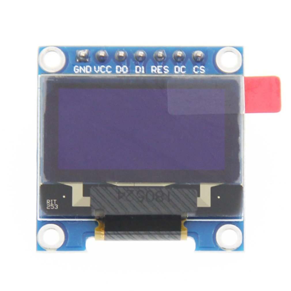
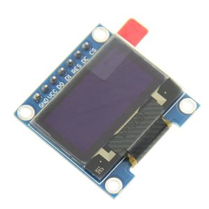
The 0.96-inch 7-Pin Blue OLED Display Module is a compact, high-contrast graphic display featuring the SSD1306 driver IC and a crisp 128×64 pixel resolution . This 7-pin variant offers the greatest flexibility, supporting both SPI and IIC communication protocols, with SPI selected by default . The dedicated CS (Chip Select) pin allows you to use multiple devices on the same SPI bus without conflicts.
OLED (Organic Light-Emitting Diode) technology requires no backlight, as each pixel emits its own light. This results in true blacks (inactive pixels are completely off), an exceptional >160° viewing angle, and significantly lower power consumption than traditional LCDs .
This module is ideal for Arduino, ESP32, ESP8266, STM32, and Raspberry Pi projects. Common applications include sensor monitors, IoT dashboards, menu interfaces for handheld devices, data loggers, and diagnostic tools .
Key Features
-
128×64 Pixel Resolution: High-definition display delivers crisp text, custom graphics, and detailed bitmaps
-
2-in-1 Communication Flexibility: Supports both SPI (default) and IIC protocols—switchable by moving a surface-mount resistor on the back
-
Blue Monochrome OLED: Vibrant blue pixels on true black background for exceptional readability
-
Dedicated CS Pin: Independent Chip Select line enables multiple SPI devices on the same bus without conflicts
-
SSD1306 Driver IC: Industry-standard controller with built-in display buffer and extensive library support
-
Wide Voltage Compatibility: Operates on 3V-5V DC, compatible with both 3.3V (ESP32) and 5V (Arduino) logic
-
Ultra-Low Power Consumption: Uses approximately 0.08W (full screen lit) since no backlight is needed
-
Wide Viewing Angle: >160° visibility ensures clear readouts from almost any angle
-
Wide Operating Temperature: Industrial-grade rating of -40°C to +85°C
Technical Specifications
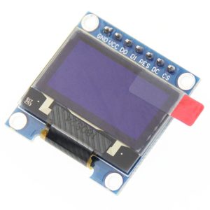
Pinout & Interface Guide
The 7-pin interface offers the full feature set, including a dedicated Chip Select (CS) pin for multi-device SPI bus configurations . Pin names may vary slightly between manufacturers—verify the silkscreen on your specific board.
Note: For IIC mode, D0 becomes the clock line (SCL), D1 becomes the data line (SDA), and DC is used to configure the IIC address .
SPI vs. IIC Protocol Selection
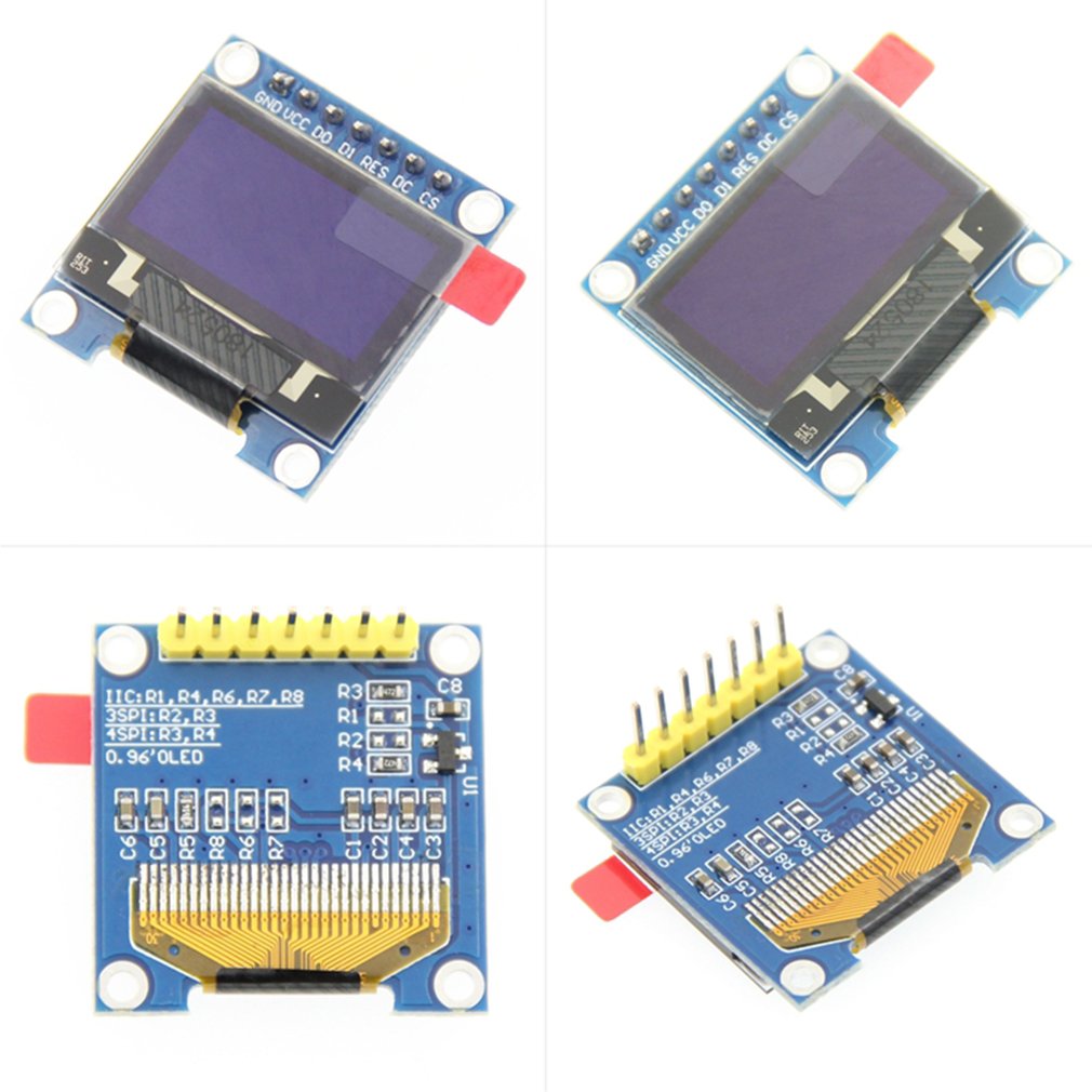
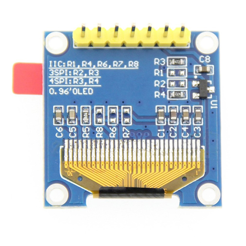
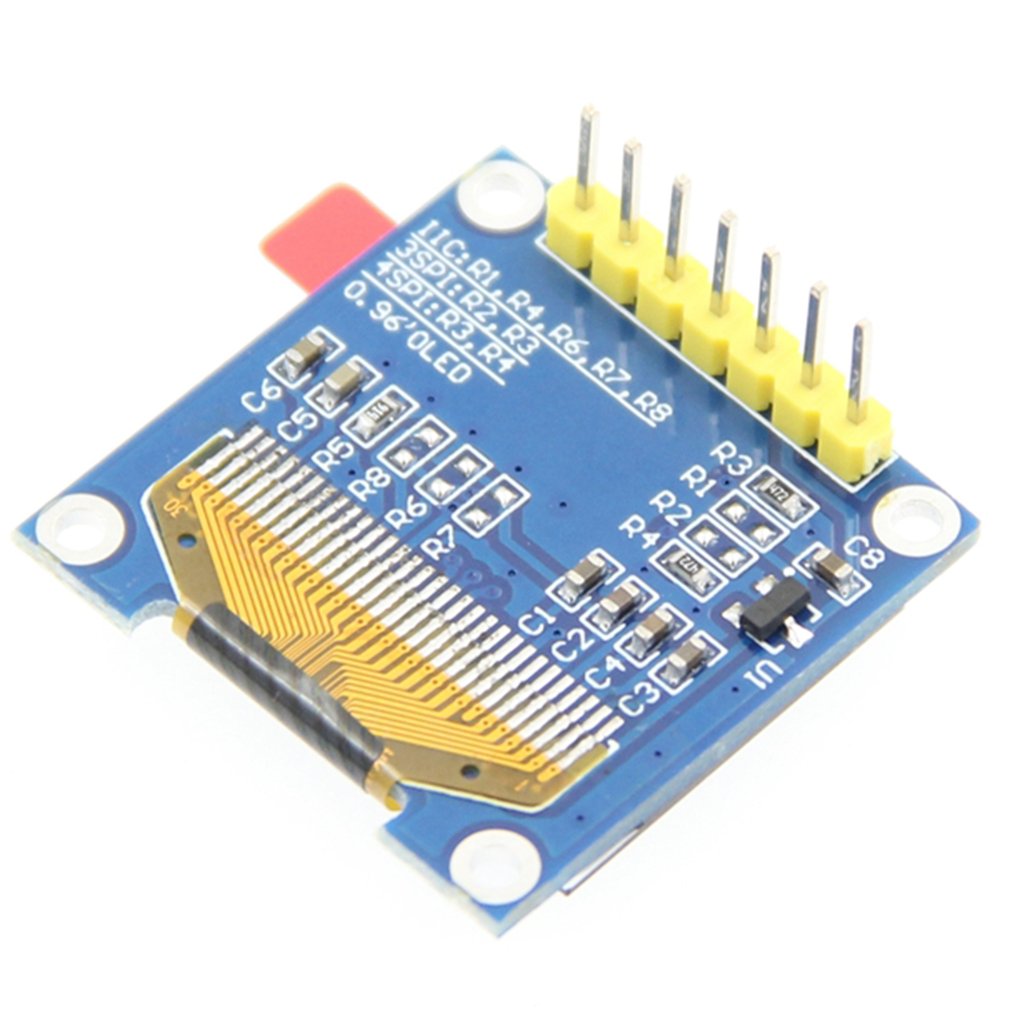
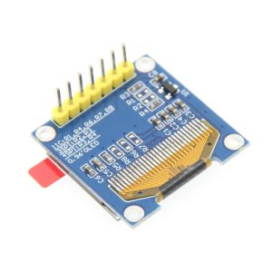
The 7-pin module uses jumper resistors on the back to select between SPI and IIC modes. By default, it comes configured for 4-wire SPI communication .
Hardware Modification Steps (to enable IIC):
-
Locate resistor positions R1, R2, R3, R4, and R8 on the back of the PCB
-
Move the resistor from R3 to R1 position (to set communication protocol)
-
Short resistor R8 with solder (to properly route IIC signals)
-
Connect CS pin to GND (disables SPI chip selection for IIC mode)
-
Connect DC pin to GND (sets IIC address to 0x78)
⚠️ Warning: Attempting to change protocols without proper rework will result in erratic behavior or no display output. Stick to the default SPI mode if you lack SMD soldering experience.
SPI Pin Mapping for Common Development Boards
CS, DC, RES Pins: The CS (Chip Select), DC (Data/Command), and RES (Reset) pins can be connected to any available GPIO. Select pins that don’t conflict with other SPI devices .
Usage Guide
Hardware Setup (SPI Mode – Default)
-
Connect Power: VCC → 5V (or 3.3V for ESP32), GND → GND.
-
Connect SPI Pins: D0 (SCK) to hardware SPI clock (Uno Pin 13), D1 (MOSI) to hardware MOSI (Uno Pin 11).
-
Connect Control Pins: RES, DC, CS to any available digital pins (e.g., Pins 8, 9, 10).
-
CS Pin use: Tying CS to GND always selects the display, but that prevents other SPI devices from sharing the bus. For single-device setups, it is functional but not best practice. Keep CS connected to a dedicated GPIO to follow correct SPI protocol.
Software Setup (Arduino IDE)
The SSD1306 is supported by several popular libraries. Adafruit_SSD1306 is the most common and well-documented for beginners, while U8g2 offers more fonts.
Installing the Adafruit SSD1306 Library
-
Open Arduino IDE → Sketch → Include Library → Manage Libraries
-
Search for and install:
Basic Test Sketch (SPI – Hardware SPI)
After installing the libraries, use this sketch to verify your display is working:
#include <SPI.h>
#include <Adafruit_GFX.h>
#include <Adafruit_SSD1306.h>
#define SCREEN_WIDTH 128
#define SCREEN_HEIGHT 64
#define OLED_DC 9
#define OLED_CS 10
#define OLED_RESET 8
Adafruit_SSD1306 display(SCREEN_WIDTH, SCREEN_HEIGHT,
&SPI, OLED_DC, OLED_RESET, OLED_CS);
void setup() {
Serial.begin(9600);
if(!display.begin(SSD1306_SWITCHCAPVCC)) {
Serial.println(F("SSD1306 allocation failed"));
for(;;);
}
display.clearDisplay();
display.setTextSize(2);
display.setTextColor(SSD1306_WHITE);
display.setCursor(20, 25);
display.println("OLED Ready!");
display.display();
}
void loop() {
}
Alternative Software SPI (Bit-Bang)
If you prefer not to use hardware SPI pins, you can use the software (bit-bang) constructor :
#include <Adafruit_GFX.h>
#include <Adafruit_SSD1306.h>
#define SCREEN_WIDTH 128
#define SCREEN_HEIGHT 64
#define OLED_MOSI 9
#define OLED_SCLK 10
#define OLED_DC 11
#define OLED_CS 12
#define OLED_RESET 13
Adafruit_SSD1306 display(SCREEN_WIDTH, SCREEN_HEIGHT,
OLED_MOSI, OLED_SCLK, OLED_DC, OLED_RESET, OLED_CS);
Using the U8g2 Library (Alternative)
The U8g2 library is another popular option that offers more fonts and advanced graphics features. Install via Library Manager, then use:
#include <Arduino.h>
#include <U8g2lib.h>
#include <SPI.h>
U8G2_SSD1306_128X64_NONAME_F_4W_SW_SPI u8g2(U8G2_R0, 13, 11, 10, 9, 8);
void setup() {
u8g2.begin();
}
void loop() {
u8g2.firstPage();
do {
u8g2.setFont(u8g2_font_ncenB08_tr);
u8g2.drawStr(0, 20, "Hello World!");
} while ( u8g2.nextPage() );
delay(1000);
}
Power Management for Battery-Powered Projects
OLED displays are excellent for low-power applications because only lit pixels consume power .
Power-Saving Tips:
-
Update the display only when values change rather than continuously refreshing
-
Use display.ssd1306_command(0xAE) to turn the display OFF when not actively updating, and 0xAF to turn back ON
-
Avoid displaying large white or high-density areas continuously to maximize battery life
Q: What is the advantage of the 7-pin (with CS) version over the 6-pin version?
The dedicated CS (Chip Select) pin allows you to connect multiple SPI devices (e.g., SD card, another display, sensors) to the same SPI bus without communication conflicts. When CS is HIGH, the display ignores the bus. This makes it the right choice for complex projects with several SPI peripherals. If you only need one display and no other SPI devices, the 6-pin version works fine .
Q: Can I use both SPI and IIC without modifying the module?
No. The module’s resistors must be reconfigured to switch between SPI and IIC modes . By default, it arrives in 4-wire SPI mode. Converting to IIC requires soldering skills to move surface-mount resistors (R3 to R1) and shorting R8.
Q: What is the benefit of SPI over IIC for this display?
SPI communication is generally faster and requires less CPU overhead than IIC. For applications with animations, rapid screen updates, or large amounts of data, SPI provides smoother performance .
Q: Does the blue display have the same power consumption as the white or yellow-blue version?
All monochrome OLED variants (blue, white, yellow-blue dual-color) have similar power profiles. Power consumption depends primarily on how many pixels are lit, not the color. The yellow-blue version uses different materials for the top and bottom sections, but per-pixel power usage is comparable .
Q: How many characters can the display show?
With the default 8×8 pixel font, approximately 16 characters × 8 lines = 128 characters total. With larger fonts (e.g., 16×16 pixels), about 8 characters × 4 lines = 32 characters. The 128×64 resolution is well-suited for dashboards and menu interfaces.
Q: What is the lifespan of the OLED display?
OLEDs have a rated lifespan of approximately 20,000-30,000 hours of continuous operation (about 2.5-3.5 years). Displaying the same static image for extremely long periods may cause “burn-in”, which is more noticeable on OLEDs than LCDs. For typical intermittent hobbyist use, this is not a concern.
Q: Why does my display stay blank after power-up?
This usually indicates one of these issues:
-
Wrong wiring – Verify VCC→5V (or 3.3V), GND→GND, D0→13, D1→11, RES→8, DC→9, CS→10
-
Incorrect library configuration – Ensure you are using the SPI constructor (not the I2C version)
-
Missing display.display() call – Drawing functions write to a buffer; you must call display.display() to push the buffer to the screen
-
Power supply – Ensure your power source can deliver ~30mA
-
CS pin not connected – If CS is floating (not connected), the display may remain deselected. Tie it to GND if not using a dedicated GPIO, or connect to a pin driven LOW
Q: Can I use this display with ESP32 or ESP8266?
Yes. Use 3.3V power (not 5V). Connect D0 to an SPI clock pin (default VSPI SCLK=18), D1 to MOSI (default 23), and the control pins to any GPIO. The Adafruit and U8g2 libraries support these platforms .
Q: Why does the display show white noise or garbled content?
This usually indicates a timing or initialization issue. Common fixes:
-
Ensure RES pin is properly driven—The OLED needs a reset pulse before initialization. The library handles this if RES is correctly connected
-
Try a slower SPI clock speed (lower than 4MHz)
-
Verify that DC and CS pins are not swapped in wiring
-
Try a different library (U8g2 vs Adafruit)
Q: Can I share the SPI bus with other devices (e.g., SD card)?
Yes. The CS pin enables this. Connect all devices to the same SCK and MOSI lines, but give each device a unique CS pin. When communicating with one device, set its CS LOW and set all other devices’ CS HIGH .
Q: How do I wire the display for the simplest possible test?
For fastest validation without other SPI devices:
-
VCC → 5V (or 3.3V)
-
GND → GND
-
D0 → 13
-
D1 → 11
-
CS → GND (tie directly to ground—keeps display always selected)
-
DC → any digital pin (e.g., D9)
-
RES → any digital pin (e.g., D8)
Using this setup, the display ignores proper SPI protocol, but proves that the panel and SPI lines function.
Q: What libraries are available for the SSD1306?
Popular options include:
-
Adafruit_SSD1306 (paired with Adafruit_GFX) – Most popular, well-documented, great for beginners
-
U8g2 – More fonts, advanced features, slightly steeper learning curve
-
SSD1306Ascii – Lightweight and fast for text-only applications
Q: Why does the Adafruit example show I2C pins in comments?
The Adafruit library supports both I2C and SPI. If your code isn’t working, verify you are using the correct constructor. The SPI constructors include parameters for CS, DC, RESET, and optionally MOSI/SCLK :
Adafruit_SSD1306 display(OLED_DC, OLED_RESET, OLED_CS);
Adafruit_SSD1306 display(OLED_MOSI, OLED_SCLK, OLED_DC, OLED_RESET, OLED_CS);
Q: Can I display images on this OLED?
Yes. Use tools like LCD Image Converter, Image2CPP, or online converters to transform 128×64 monochrome bitmap images into C arrays. Then use display.drawBitmap(x, y, array, width, height, color) to display them.
Q: Does the library work with the Raspberry Pi?
Yes, this display works with Raspberry Pi using Python libraries such as Adafruit_CircuitPython_SSD1306 or Luma.OLED. Enable SPI via raspi-config, then connect VCC to 3.3V (Pin 1) and the SPI pins accordingly .