Product Overview
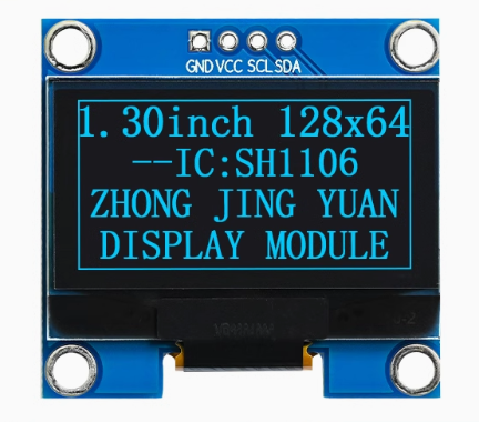
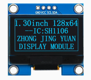
The 1.3-inch Blue SPI OLED Display Module is a compact, high-contrast monochrome screen designed for embedded applications requiring crisp visual output and fast refresh rates. Powered by the SH1106 driver IC and featuring a sharp 128×64 pixel resolution, this display delivers vibrant blue text, detailed graphics, and custom icons on a true black background .
This 6-pin SPI version offers significantly faster data transfer compared to I2C versions, making it ideal for applications requiring smooth animations, frequent screen updates, or displaying large amounts of data. The dedicated RES (Reset) and DC (Data/Command) pins provide full independent control of the display, ensuring reliable operation .
OLED (Organic Light Emitting Diode) technology requires no backlight, as each pixel emits its own light. This self-emissive design provides true blacks (inactive pixels are completely off), an exceptional contrast ratio (10,000:1 typical), and >160° viewing angles – ensuring the display remains readable from virtually any angle .
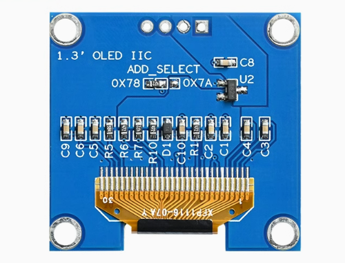
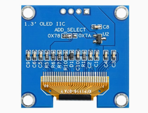
The module’s default interface is 4-wire SPI, but it can be switched to 3-wire SPI or I2C by adjusting resistors on the back of the PCB . With support for both 3.3V and 5V power supply, this module works with Arduino (with level shifters for 5V logic), ESP32, ESP8266, STM32, Raspberry Pi, and most other development boards .
Key Features
-
1.3-Inch Active Area: 29.42mm × 14.7mm display area offers better readability than 0.96″ screens while maintaining 128×64 resolution
-
128×64 Pixel Resolution: High-definition display capable of showing detailed graphics, bitmaps, custom icons, and up to 8 lines of text
-
Blue Monochrome OLED: Vibrant blue pixels on true black background provide excellent contrast and professional appearance
-
SH1106 Driver IC: Industry-standard controller with built-in 132×64-bit SRAM buffer, designed specifically for 128×64 displays
-
SPI Interface (Fast): 4-wire SPI communication provides faster data transfer than I2C – ideal for animations and frequent screen updates
-
Independent Control Pins: Dedicated RES (Reset) and DC (Data/Command) pins for full display control
-
Dual Communication Options: Supports SPI (default) and I2C (by resistor modification) – flexible for different project needs
-
Wide Voltage Compatibility: Accepts 3.3V–5.5V power supply (VCC) – compatible with both 5V and 3.3V systems
-
⚠️ Logic Level Warning: SPI logic pins are 3.3V only – use level shifters with 5V microcontrollers
-
Wide Operating Temperature: Rated for -40°C to +70°C, suitable for demanding environments
Technical Specifications
Pinout & Connection Guide
The 6-pin SPI interface uses standard pin functions for easy connection. Pin labeling may vary slightly between manufacturers; always verify the silkscreen on your specific board.
Pin Definitions (6-Pin)
Connection to 3.3V Microcontrollers (ESP32, Raspberry Pi)
Logic voltage matches – direct connection, no level shifters needed.
Connection to 5V Microcontrollers (Arduino Uno)
⚠️ CRITICAL: The logic pins (SCL, SDA, RES, DC) are NOT 5V tolerant. You MUST use 3.3V logic level shifters on these pins . VCC power pin IS 5V tolerant and can be connected directly to 5V.
I2C Mode Modification
The module can be switched to I2C mode by modifying resistors on the back of the PCB :
When using I2C mode:
-
Connect SDA to the appropriate data pin and SCL to the clock pin
-
Set DC pin configuration as shown in hardware guide
-
I2C address is typically 0x3C (write) / 0x3D (read) when DC is grounded
Usage Guide
Software Setup (Arduino IDE)
Step 1: Install Required Libraries
The U8g2 library is the most reliable choice for SH1106 SPI displays, offering excellent support and many font options .
-
Open Arduino IDE → Sketch → Include Library → Manage Libraries
-
Search for “U8g2” by Oliver Kraus
-
Click Install
Step 2: Basic Test Sketch (U8g2 Library – Hardware SPI)
For ESP32 / 3.3V boards (direct connection):
#include <Arduino.h>
#include <U8g2lib.h>
#include <SPI.h>
U8G2_SH1106_128X64_NONAME_1_4W_HW_SPI u8g2( U8G2_R0, 15, 2, 4);
void setup() {
u8g2.begin();
u8g2.enableUTF8Print();
u8g2.setFont(u8g2_font_ncenB08_tr);
u8g2.setDrawColor(1);
}
void loop() {
u8g2.firstPage();
do {
u8g2.drawStr(0, 15, "1.3 OLED");
u8g2.drawStr(0, 35, "128x64");
u8g2.drawStr(0, 55, "SH1106");
} while ( u8g2.nextPage() );
delay(1000);
}
Note: If your module has a CS (Chip Select) pin, include it in the constructor as the 3rd parameter. For 6-pin modules without CS (always selected), the U8g2 library may require a dummy pin value.
Step 3: Alternative: U8g2 with Software SPI (Any Pins)
If you prefer not to use hardware SPI pins:
#include <Arduino.h>
#include <U8g2lib.h>
U8G2_SH1106_128X64_NONAME_1_4W_SW_SPI u8g2(U8G2_R0, 13, 11, 10, 9, 8);
void setup() {
u8g2.begin();
u8g2.setFont(u8g2_font_ncenB08_tr);
}
void loop() {
u8g2.firstPage();
do {
u8g2.drawStr(0, 20, "Hello SH1106!");
} while ( u8g2.nextPage() );
delay(1000);
}
Raspberry Pi Setup
-
Enable SPI via raspi-config → Interface Options → SPI → Yes
-
Install required libraries:
sudo apt-get install python3-pip
pip3 install luma.oled
-
Python example code:
from luma.core.interface.serial import spi
from luma.oled.device import sh1106
from luma.core.render import canvas
serial = spi(port=0, device=0, gpio_DC=24, gpio_RST=25)
device = sh1106(serial)
with canvas(device) as draw:
draw.rectangle(device.bounding_box, outline="white", fill="black")
draw.text((30, 20), "1.3 OLED", fill="white")
draw.text((30, 40), "SPI 128x64", fill="white")
Important Note: Charge Pump
For proper operation, the SH1106’s internal charge pump must be enabled. Most libraries do this automatically, but if your display remains off, add:
u8g2.sendCommand(0x8D);
u8g2.sendCommand(0x14);
SH1106 vs SSD1306 Difference
The SH1106 driver has internal RAM of 132×64 pixels, while the visible area is 128×64 pixels. When using the display, note that the column start address needs to be set to 0x02 (unlike SSD1306 which uses 0x00) . Most modern libraries (U8g2, Adafruit_SH110X) handle this automatically.
Power Management for Battery-Powered Projects
Only lit pixels consume power, making OLEDs excellent for battery-powered applications.
Q: What is the difference between this 1.3" SPI OLED and the 0.96" version?
The 1.3″ version has a larger active area (29.42mm × 14.7mm vs 21.74mm × 10.86mm) while maintaining the same 128×64 resolution, resulting in larger, more readable pixels. Additionally, the 1.3″ typically uses the SH1106 driver, while 0.96″ often uses SSD1306
Q: Can I use an SSD1306 library with this SH1106 display?
Most SSD1306 libraries may work, but they may not handle the SH1106’s offset correctly (SH1106 has 132×64 internal RAM with a column start address of 0x02 vs SSD1306’s 0x00) . For guaranteed compatibility, use libraries that explicitly support SH1106, such as U8g2 (recommended) or Adafruit SH110X .
Q: What is the advantage of SPI over I2C for this display?
SPI is significantly faster. SPI allows much faster data transfer, making it ideal for animations, rapid screen updates, or real-time data dashboards. The default interface is 4-wire SPI, offering the best performance .
Q: Can I switch this display to I2C mode?
Yes. The module supports 3-wire SPI, 4-wire SPI, and I2C interfaces. By adjusting the resistors on the back of the PCB, you can switch to I2C mode . The default configuration is 4-wire SPI .
Q: Can I connect this display directly to a 5V Arduino (Uno, Mega, etc.)?
NO! The SPI logic pins (CLK, MOSI, RES, DC) are NOT 5V tolerant and require 3.3V logic. Using 5V directly will damage the display . However, the VCC power pin IS 5V tolerant. You must use 3.3V logic level shifters on SCL, SDA, RES, and DC pins when using 5V microcontrollers .
Q: Can I use this display with ESP32 or Raspberry Pi?
Yes – both ESP32 and Raspberry Pi use 3.3V logic, which matches the display’s requirements for logic signals. Connect directly without level shifters. Use 3.3V power for VCC as well .
Q: Can I power the display from 3.3V instead of 5V?
Yes. VCC accepts 3.3V–5.5V, so 3.3V power works perfectly and may simplify your wiring when using 3.3V logic microcontrollers .
Q: Why does my display stay blank after power-up?
Common issues to check:
-
Logic voltage mismatch – if using 5V Arduino, did you use level shifters?
-
Wiring – verify VCC power, GND connections
-
Library initialization – ensure you’re using a SH1106-compatible library
-
Charge pump – the internal charge pump must be enabled (most libraries handle this)
-
SPI pins – verify CLK and MOSI are connected to the correct pins
Q: How many characters can the display show?
With the default 8×8 pixel font, approximately 16 characters × 8 lines = 128 characters total. With larger fonts (e.g., 16×16 pixels), about 8 characters × 4 lines = 32 characters.
Q: What is the lifespan of the OLED display?
Rated lifespan is approximately 20,000-30,000 hours of continuous operation (about 2.5-3.5 years) . Avoid displaying static images for extremely long periods to prevent uneven pixel wear.