Product Overview
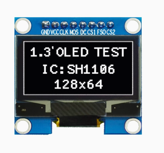
The 1.3-inch Blue 8-Pin OLED Display Module is a high-performance monochrome graphic display featuring the SH1106 driver IC from Sino Wealth, designed for embedded applications requiring crisp visual output and flexible connectivity . With a sharp 128×64 pixel resolution, this 8-pin variant provides the most comprehensive interface options, supporting both SPI (3-wire/4-wire) and I2C communication protocols, as well as 8-bit parallel interfaces for maximum versatility .
The key distinguishing feature of this 8-pin module is the inclusion of both CS1 (Chip Select 1) and CS2 (Chip Select 2) pins, which in addition to the SO (Serial Data Out) pin, allow for advanced communication modes and multi-device bus sharing without conflicts. The multiple chip select lines enable this module to function seamlessly in complex projects with multiple peripherals sharing the same SPI bus.
OLED (Organic Light Emitting Diode) technology requires no backlight, as each pixel emits its own light. This self-emissive design delivers true blacks (inactive pixels are completely off), exceptional contrast (>2000:1), and >160° viewing angles . The bright blue monochrome display ensures excellent readability in all lighting conditions while consuming minimal power.
The module includes an embedded 132×64-bit SRAM display buffer and an on-chip oscillator, reducing external component requirements . With a built-in charge pump circuit generating the necessary OLED driving voltage, the module requires only a single 3.3V–5.5V power supply, making it compatible with both 5V (Arduino) and 3.3V (ESP32, Raspberry Pi) systems .
Key Features
-
Multiple Interface Options: Supports 3-wire SPI, 4-wire SPI, I2C (400kHz), and 8-bit parallel interfaces – the most flexible 1.3-inch OLED module available
-
Dual Chip Select Lines: Features both CS1 and CS2 pins for advanced multi-device SPI bus configurations – enables seamless sharing with other peripherals
-
128×64 Pixel Resolution: High-definition display with 1.3″ active area (29.42mm × 14.7mm) – capable of showing detailed graphics, bitmaps, and up to 8-16 lines of text
-
Blue Monochrome OLED: Vibrant blue pixels on true black background provide excellent contrast and professional “Sci-Fi” appearance
-
SH1106 Driver IC: Industry-standard controller with embedded 132×64-bit SRAM, on-chip oscillator, and programmable internal charge pump
-
Wide Voltage Compatibility: Accepts 3.3V–5.5V power supply – works with both 5V (Arduino) and 3.3V (ESP32, Raspberry Pi) systems
-
Ultra-Low Power Consumption: Sleep mode current <5μA; typical operating current ~20mA – ideal for battery-powered projects
-
256-Step Contrast Control: Programmable contrast adjustment for optimal visibility in any lighting condition
-
Wide Operating Temperature: Rated for -40°C to +85°C – suitable for industrial and outdoor applications
-
Mounting Holes: 4 mounting holes for secure installation in enclosures and projects
Technical Specifications
Pinout & Connection Guide
Pin Definitions (8-Pin SPI/I2C Configuration)
Note: The SO pin can be used for readback operations in SPI mode. When not used, it can be left disconnected. The dual CS pins allow this module to be used alongside other SPI devices without conflicts .
Interface Mode Selection
The SH1106 supports multiple interface modes, configurable via hardware strapping :
Connection to 3.3V Microcontrollers (ESP32, Raspberry Pi)
Logic voltage matches – no level shifters needed.
Connection to 5V Microcontrollers (Arduino Uno)
⚠️ CRITICAL: The logic pins are NOT 5V tolerant. You must use 3.3V logic level shifters on all logic pins except VCC. The VCC power pin IS 5V tolerant .
Alternative: Use a 3.3V board (ESP32, Arduino Pro Mini 3.3V, Raspberry Pi) to avoid level shifters entirely .
Usage Guide
Software Setup (Arduino IDE)
Step 1: Install Required Libraries
The U8g2 library by Oliver Kraus is the most reliable choice for SH1106 displays, offering excellent support and many font options .
-
Open Arduino IDE → Sketch → Include Library → Manage Libraries
-
Search for “U8g2” by Oliver Kraus
-
Click Install
Alternative Libraries:
-
Adafruit SH110X – Good for basic graphics, simpler syntax
-
SSD1306Ascii – Lightweight, text-only applications
Step 2: Basic Test Sketch (Hardware SPI Mode)
For ESP32 / 3.3V microcontrollers :
#include <Arduino.h>
#include <U8g2lib.h>
#include <SPI.h>
U8G2_SH1106_128X64_NONAME_1_4W_HW_SPI u8g2(U8G2_R0, 5, 2, 4);
void setup() {
u8g2.begin();
u8g2.enableUTF8Print();
u8g2.setFont(u8g2_font_ncenB08_tr);
u8g2.setDrawColor(1);
}
void loop() {
u8g2.firstPage();
do {
u8g2.drawStr(0, 15, "1.3 OLED");
u8g2.drawStr(0, 35, "128x64");
u8g2.drawStr(0, 55, "SH1106 8-Pin");
u8g2.drawStr(0, 75, "SPI Mode");
} while ( u8g2.nextPage() );
delay(1000);
}
Step 3: Software SPI Mode (Any Pins – No Hardware SPI Required)
If you prefer not to use hardware SPI pins :
#include <Arduino.h>
#include <U8g2lib.h>
U8G2_SH1106_128X64_NONAME_1_4W_SW_SPI u8g2(U8G2_R0, 13, 11, 10, 9, 8);
void setup() {
u8g2.begin();
u8g2.setFont(u8g2_font_ncenB08_tr);
}
void loop() {
u8g2.firstPage();
do {
u8g2.drawStr(0, 20, "SH1106 Ready!");
} while ( u8g2.nextPage() );
delay(1000);
}
Step 4: I2C Mode Connection
For I2C mode (requires resistor configuration on PCB) :
#include <Arduino.h>
#include <U8g2lib.h>
#include <Wire.h>

U8G2_SH1106_128X64_NONAME_F_HW_I2C u8g2(U8G2_R0, U8X8_PIN_NONE);

void setup() {
  u8g2.begin();
  u8g2.setFont(u8g2_font_ncenB08_tr);
}

void loop() {
  u8g2.firstPage();
  do {
    u8g2.drawStr(0, 20, "I2C Mode");
  } while ( u8g2.nextPage() );
  delay(1000);
}
Raspberry Pi Setup (Python)
-
Enable SPI: sudo raspi-config → Interface Options → SPI → Yes
-
Install required libraries:
sudo apt-get install python3-pip
pip3 install luma.oled
-
Python example code:
from luma.core.interface.serial import spi
from luma.oled.device import sh1106
from luma.core.render import canvas
serial = spi(port=0, device=0, gpio_DC=24, gpio_RST=25, gpio_CS=8)
device = sh1106(serial)
with canvas(device) as draw:
draw.rectangle(device.bounding_box, outline="white", fill="black")
draw.text((30, 20), "1.3 OLED", fill="white")
draw.text((30, 40), "128x64", fill="white")
Important: SH1106 vs SSD1306 Differences
The SH1106 driver is the correct choice for 1.3″ OLED displays. Unlike SSD1306 (used on 0.96″ displays), SH1106 has internal RAM of 132×64 pixels, while the visible area is 128×64 pixels . Most modern libraries (U8g2, Adafruit) handle this automatically, but if you see horizontal misalignment, you may need to adjust the start column address.
Key differences :
-
SH1106 requires a column start address of 0x02 (vs SSD1306’s 0x00)
-
Charge pump initialization commands differ between the two drivers
-
Always use SH1106-compatible libraries for 1.3″ displays
U8g2 Display Buffer Workflow
U8g2 uses a page-buffered approach to manage memory efficiently :
u8g2.firstPage();
do {
u8g2.drawStr(0, 20, "Hello");
} while ( u8g2.nextPage() );
This structure allows the same code to work on both full-buffer and low-memory devices. The _1_ constructors (vs _F_) use less RAM but require page looping .
Power Management for Battery-Powered Projects
Only lit pixels consume power, making OLEDs excellent for battery-powered applications :
Power-Saving Tips:
-
Use u8g2.setPowerSave(1) to put display in sleep mode when not needed
-
Update the display only when values change rather than continuously refreshing
-
Consider using I2C mode for battery-powered applications (slightly lower power, fewer pins)
Q: What is the advantage of the 8-pin version over 4-pin or 6-pin OLED modules?
The 8-pin version offers the most flexibility with multiple interface options: 3-wire SPI, 4-wire SPI, I2C, and 8-bit parallel . The dual chip select pins (CS1 and CS2) allow this module to easily coexist with other SPI devices on the same bus. The additional SO pin enables readback operations, allowing you to read data back from the display (useful for debugging).
Q: Can I use this display with a 5V Arduino Uno directly?
NO! The logic pins (SCK, MOSI, DC, RST, CS1) are NOT 5V tolerant. You must use 3.3V logic level shifters on all these pins . However, the VCC power pin IS 5V tolerant and can connect directly to 5V. For beginners, using a 3.3V board (ESP32, Raspberry Pi) is strongly recommended to avoid level shifters.
Q: What is the difference between SH1106 and SSD1306 drivers?
The SH1106 has internal RAM of 132×64 pixels, while the visible area is 128×64 pixels . SH1106 is designed for 1.3″ displays and larger, while SSD1306 is typically used on 0.96″ displays . The initialization commands (especially for the charge pump) differ between the two, so always use SH1106 libraries for this display.
Q: Why does my display show a white line on the side or shifted content?
This is a common SH1106 characteristic. The driver has 4 extra columns of internal RAM that are not displayed. If you see a white line on the left edge, you can apply a software offset by adding 2 to your column start address . The U8g2 library handles this automatically for SH1106.
Q: Can I use this display with ESP32 and ESP8266?
Yes – both ESP32 and ESP8266 use 3.3V logic, which matches the display’s logic requirements. Connect directly without level shifters. Use 3.3V power for VCC as well. The U8g2 library works on both platforms with the same code .
Q: How do I enable Chinese character display on this OLED?
The U8g2 library supports UTF-8 encoding. Enable it with u8g2.enableUTF8Print(), then use fonts that include Chinese characters (e.g., u8g2_font_wqy12_t from WenQuanYi) . For custom characters, use font extraction tools to generate your own bitmap font arrays.
Q: My display stays blank even though the library initializes successfully. What should I check?
Check these common issues :
-
Interface mode – Ensure the module is configured for the mode you’re using (check resistor settings)
-
Wiring – Verify VCC and GND connections
-
Library – Ensure you selected SH1106 driver in U8g2 (not SSD1306)
-
Charge pump – The SH1106 requires charge pump enable command (most libraries handle this, but verify)
-
Reset sequence – Power-on reset pulse may be needed; try adding a delay after power-up
-
I2C address – If using I2C, try 0x3C if 0x3D doesn’t work, and vice versa
Q: Which library provides the best performance – U8g2 or Adafruit?
U8g2 offers more features (more fonts, better SH1106 support) but has slightly higher RAM usage . Adafruit SH110X is simpler and more beginner-friendly but has fewer fonts and features. For most 1.3″ SH1106 applications, U8g2 is recommended due to its comprehensive SH1106 support .
Q: What is the lifespan of the OLED display?
Rated lifespan is approximately 20,000-30,000 hours of continuous operation (about 2.5-3.5 years) . Avoid displaying static images for extremely long periods to prevent uneven pixel wear (“burn-in”). For typical intermittent hobbyist use, this is not a concern.
Q: Can I use this display to show real-time sensor data and animations?
Yes. The 1.3″ SH1106 offers good performance for real-time data. For optimal results use SPI mode (faster than I2C) and the _F_ (full buffer) constructors in U8g2, which provide the smoothest refresh rates . Typical refresh rates can achieve 10-30fps for partial updates – suitable for graphs, dashboards, and simple animations .