Product Overview
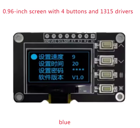
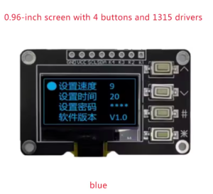
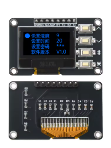
The 0.96-inch OLED Display Module is a compact, high-contrast monochrome graphic display that combines a 128×64 pixel OLED screen with a 4-key tactile keypad interface on a single PCB. Powered by the advanced SSD1315 driver IC, this module provides a complete human-machine interface (HMI) solution for embedded projects .
This all-in-one module is designed to simplify your project wiring. Instead of connecting a display and a keypad separately—which would consume multiple I/O pins—this module integrates both components and communicates via the I2C protocol, requiring only two data lines (SDA and SCL) to control both the screen and read key presses . This leaves your microcontroller’s valuable I/O pins free for other sensors and peripherals.
OLED (Organic Light Emitting Diode) technology requires no backlight, as each pixel emits its own light. This self-emissive design provides true blacks (inactive pixels are completely off), excellent contrast, and wide viewing angles (>160°) . The bright blue monochrome display ensures excellent readability in all lighting conditions while consuming minimal power—only lit pixels consume energy, making it ideal for battery-powered applications.
The module operates on 3.3V logic, making it directly compatible with ESP32, ESP8266, Raspberry Pi, STM32, and other 3.3V microcontrollers. The SSD1315 driver supports I2C clock speeds up to 1MHz . The four tactile buttons provide responsive user input for menu navigation, mode selection, or data entry without requiring additional components.
Key Features
-
Integrated Display + Keypad: Combines a 0.96″ 128×64 OLED display with 4 tactile push buttons on a single PCB – a complete HMI solution
-
I2C Communication: Both the display and the keypad share the same I2C bus, using only 2 pins (SDA/SCL) for control – saves GPIO resources
-
Blue Monochrome OLED: Bright blue pixels on true black background provide excellent contrast and wide viewing angles (>160°)
-
SSD1315 Driver IC: Next-generation driver with built-in 128×64-bit SRAM buffer, supports I2C up to 1MHz
-
3.3V Logic Voltage: Directly compatible with ESP32, ESP8266, Raspberry Pi, STM32, and other 3.3V microcontrollers
-
Ultra-Low Power Consumption: Self-emissive OLED technology consumes power only on lit pixels – ideal for battery-powered projects
-
Wide Operating Temperature: Rated for -40°C to +85°C, suitable for industrial and outdoor applications
-
Complete Documentation Support: Compatible with popular libraries including U8g2 for Arduino and luma.oled for Raspberry Pi
Technical Specifications
Pinout & Connection Guide
The module features a 4-pin I2C interface for easy connection to your microcontroller.
Pin Definitions (4-Pin)
I2C Pin Mapping for Common Development Boards
Wiring Diagram (ESP32)
OLED Module          →    ESP32
─────────────────────────────────────
VCC                  →    3.3V
GND                  →    GND
SCL                  →    GPIO22 (SCL)
SDA                  →    GPIO21 (SDA)
Important Electrical Notes:
-
This module operates at 3.3V only. Do not connect VCC to 5V.
-
The four tactile buttons are connected to the I2C bus via pull-up resistors . They share the same SDA/SCL lines as the display.
-
If you need to add multiple I2C devices, be aware that the buttons add capacitance to the bus (approximately 85pF with three devices) . An I2C multiplexer may be required for complex multi-device setups.
Usage Guide
Software Setup (Arduino IDE)
Step 1: Install Required Libraries
The U8g2 library by Oliver Kraus is the most reliable choice for SSD1315 displays, offering excellent support and many font options.
-
Open Arduino IDE → Sketch → Include Library → Manage Libraries
-
Search for “U8g2” by Oliver Kraus
-
Click Install
-
(Optional) For keypad support, install “Adafruit Keypad” library
Step 2: Basic Test Sketch
#include <Arduino.h>
#include <U8g2lib.h>
#include <Wire.h>
U8G2_SSD1306_128X64_NONAME_F_HW_I2C u8g2(U8G2_R0, U8X8_PIN_NONE);
void setup() {
u8g2.begin();
u8g2.enableUTF8Print();
u8g2.setFont(u8g2_font_ncenB08_tr);
}
void loop() {
u8g2.firstPage();
do {
u8g2.drawStr(0, 15, "0.96 OLED");
u8g2.drawStr(0, 35, "128x64");
u8g2.drawStr(0, 55, "SSD1315");
} while ( u8g2.nextPage() );
delay(1000);
}
Step 3: Using the 4 Keys
The four keys share the I2C bus with the display. The module uses 10kΩ pull-up resistors on the button lines . To read key presses, you can use the Adafruit Keypad library or directly read the I2C register values (consult the module’s specific documentation for register mapping).
Important Note on Debouncing: The mechanical buttons have a typical bounce time of 6.2ms ±1.4ms . For reliable key detection, implement a 10ms debounce window in your firmware to prevent false triggers.
Power Consideration: When a button is pressed, it can cause a momentary VDD drop of up to 0.3V, which may cause OLED brightness fluctuation . Adding a 0.1µF ceramic capacitor between VDD and GND near the module is recommended for stable operation.
Raspberry Pi Setup (Python)
-
Enable I2C: sudo raspi-config → Interface Options → I2C → Yes
-
Install required libraries:
sudo apt-get install python3-pip
pip3 install luma.oled
-
Python example code:
from luma.core.interface.serial import i2c
from luma.oled.device import ssd1306
from luma.core.render import canvas
serial = i2c(port=1, address=0x3C)
device = ssd1306(serial, width=128, height=64)
with canvas(device) as draw:
draw.rectangle(device.bounding_box, outline="white", fill="black")
draw.text((10, 20), "0.96 OLED", fill="white")
draw.text((10, 40), "128x64", fill="white")
Understanding the Display Buffer Workflow (U8g2)
The U8g2 library uses a page-buffered approach to manage memory efficiently:
u8g2.firstPage();
do {
u8g2.drawStr(0, 20, "Hello");
} while ( u8g2.nextPage() );
This structure allows the same code to work on both full-buffer and low-memory devices. The _F_ (full buffer) constructors use more RAM but provide smoother updates.
SSD1315 Driver Notes
The SSD1315 is the driver IC for this 0.96″ OLED module . It is compatible with the SSD1306 command set, meaning existing SSD1306 libraries (including U8g2 and Adafruit_SSD1306) will work with this display . The SSD1315 supports I2C clock speeds up to 1MHz, though many modules are limited to 400kHz for compatibility.
Key Advantage: The SSD1315 has better timing tolerance than the SSD1306, with SCL rise times of approximately 110ns compared to 280ns on SSD1306 modules . This makes it more reliable for high-speed I2C communication.
Q: Can I use this module with a 5V Arduino Uno or Mega?
No. This module is designed for 3.3V logic only. The VCC pin and I2C logic pins are NOT 5V tolerant. Connecting to 5V will damage the module. For 5V systems, use a logic level converter on SDA/SCL lines and a 3.3V regulator for power.
Q: What is the default I2C address of the display?
The default I2C address is typically 0x3C . Some modules may support address configuration via resistor jumpers. Run an I2C scanner sketch to verify the address if you have trouble detecting the device.
Q: How do the 4 keys work? Do they use additional pins?
The four tactile buttons are connected to the I2C bus through pull-up resistors and share the same SDA/SCL lines as the display . They do NOT use additional GPIO pins. However, they do add capacitance to the I2C bus (~85pF with three devices), which can affect communication stability when multiple I2C devices are connected .
Q: Why does my I2C communication fail when connected to other devices?
The button matrix adds capacitance to the I2C bus. When you have multiple I2C devices, the total bus capacitance may exceed limits, causing communication errors . Solutions: Use an I2C multiplexer to isolate the display module, or reduce the I2C clock speed to 100kHz.
Q: The buttons sometimes register false presses. How can I fix this?
This is contact bounce, a mechanical property of tactile switches. The buttons have a typical bounce time of 6.2ms ±1.4ms . Implement a 10ms software debounce in your key reading routine to eliminate false triggers. Adding a 0.1µF capacitor across VDD and GND also helps reduce voltage fluctuations during button presses.
Q: Does this module work with the Adafruit SSD1306 library?
Yes. The SSD1315 driver is command-compatible with the SSD1306 . The Adafruit_SSD1306 library (and U8g2) will work with this display. When initializing, use the same code as you would for an SSD1306-based 128×64 OLED.
Q: Can I change the I2C address if there's a conflict with another device?
Some module variants support address configuration by soldering jumpers on the back of the PCB . Check if your module has address selection pads. If not, you may need to use an I2C multiplexer or choose a different I2C address for your other device.
Q: The module gets hot during operation. Is this normal?
OLED displays generate minimal heat. If the module is hot, check your power supply voltage (must be 3.3V, not 5V). Also verify that you haven’t shorted any pins. The module should remain cool to the touch during normal operation.
Q: Can I turn off the display to save power?
Yes. The SSD1315 supports power-down mode. Send command 0xAE to turn the display OFF, and 0xAF to turn it back ON. In sleep mode, current consumption drops to <10µA. This is useful for battery-powered projects where the display is not constantly needed.
Q: Is this module suitable for industrial applications?
Yes. The module is rated for -40°C to +85°C operating temperature , making it suitable for industrial environments. However, for mission-critical applications, note that the buttons may require additional debouncing and the I2C bus may need isolation from noisy industrial environments .