Product Overview
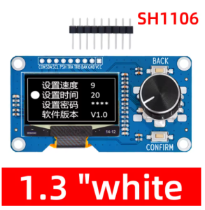
The 1.3-inch I2C OLED Display Module with EC11 Rotary Encoder is a compact, all-in-one human-machine interface (HMI) solution that combines a high-contrast 128×64 pixel OLED screen with a precise rotary encoder and tactile buttons on a single PCB . This integrated module is specifically designed for projects requiring both visual feedback and precise user input, making it ideal for menu navigation, parameter adjustment, and interactive control systems.
The module features a 1.3-inch monochrome OLED display driven by the SSD1306/SH1106 controller, communicating via the simple I2C interface using only two data lines (SDA and SCL) . The EC11 incremental rotary encoder provides smooth rotational input with 20 pulses per revolution and detents for tactile feedback, plus a push-button function for selection or confirmation actions .
OLED (Organic Light Emitting Diode) technology requires no backlight, as each pixel emits its own light. This self-emissive design provides true blacks (inactive pixels are completely off), excellent contrast, and wide viewing angles (>160°) – ensuring the display remains readable in various lighting conditions while consuming minimal power .
Whether you are building a smart thermostat, a CNC controller pendant, a digital audio interface, or an IoT configuration panel, this integrated display and encoder module provides a compact, professional solution that simplifies wiring and reduces component count.
Key Features
-
Integrated Display + Encoder: Combines a 1.3″ 128×64 OLED display with an EC11 rotary encoder (with push-button) on a single PCB – a complete HMI solution
-
I2C Communication: The OLED display uses I2C protocol (address 0x3C), requiring only 2 pins (SDA/SCL) for communication – saves valuable GPIO resources
-
EC11 Incremental Encoder: Features 20 pulses per revolution with detents for tactile feedback, plus a built-in push-button switch for selection/confirmation
-
High-Contrast OLED Display: 128×64 pixel resolution with true black background and bright monochrome pixels (white or blue options)
-
Dual Voltage Compatibility: Operates on 3.3V – 5V logic, compatible with Arduino, ESP32, ESP8266, STM32, and Raspberry Pi
-
Additional Tactile Buttons: Most variants include two extra buttons (Back/Confirm) for enhanced menu navigation
-
Compact All-in-One Design: Small PCB footprint (approximately 65×35mm) reduces wiring complexity and component clutter
-
Wide Operating Temperature: Reliable performance across various environments; OLEDs perform well in dim industrial settings and total darkness
Technical Specifications
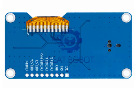
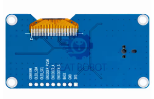
Pinout & Connection Guide
The module typically features a 9-pin interface. Pin labeling may vary slightly between manufacturers; always verify the silkscreen on your specific board.
Pin Definitions
Important: The I2C address for the OLED display is typically 0x3C. Run an I2C scanner sketch to verify if you have trouble detecting the device .
Wiring Diagram (Arduino Uno)
Wiring Diagram (ESP32)
Usage Guide
Software Setup (Arduino IDE)
Step 1: Install Required Libraries
Install the following libraries via Arduino Library Manager (Sketch → Include Library → Manage Libraries):
-
“U8g2” by Oliver Kraus – Display library (recommended, supports many fonts and both SSD1306/SH1106)
-
“Adafruit SH110X” – Alternative display library for 1.3″ screens
-
“Rotary” by Ben Buxton – Encoder reading library
-
“Button2” – Button debouncing library
Note: For 1.3″ displays, the driver IC is typically SH1106 (not SSD1306). Use SH1106 libraries for proper display alignment .
Step 2: Basic Test Sketch
#include <Arduino.h>
#include <U8g2lib.h>
#include <Wire.h>
U8G2_SH1106_128X64_NONAME_F_HW_I2C u8g2(U8G2_R0, U8X8_PIN_NONE);
#define ENC_A 2
#define ENC_B 4
#define ENC_SW 3
#define KEY_CON 5
#define KEY_BACK 6
volatile int encoderPos = 0;
bool buttonPressed = false;
void setup() {
u8g2.begin();
u8g2.enableUTF8Print();
u8g2.setFont(u8g2_font_ncenB08_tr);
pinMode(ENC_A, INPUT_PULLUP);
pinMode(ENC_B, INPUT_PULLUP);
pinMode(ENC_SW, INPUT_PULLUP);
pinMode(KEY_CON, INPUT_PULLUP);
pinMode(KEY_BACK, INPUT_PULLUP);
attachInterrupt(digitalPinToInterrupt(ENC_A), encoderISR, CHANGE);
attachInterrupt(digitalPinToInterrupt(ENC_B), encoderISR, CHANGE);
Serial.begin(115200);
}
void loop() {
u8g2.firstPage();
do {
u8g2.drawStr(0, 15, "1.3 OLED Menu");
u8g2.drawStr(0, 35, "Position: ");
u8g2.setCursor(70, 35);
u8g2.print(encoderPos);
if (digitalRead(ENC_SW) == LOW) {
u8g2.drawStr(0, 55, "Selected!");
}
} while (u8g2.nextPage());
delay(50);
}
void encoderISR() {
static unsigned long lastTime = 0;
unsigned long now = millis();
if (now - lastTime > 5) {
if (digitalRead(ENC_A) == digitalRead(ENC_B)) {
encoderPos++;
} else {
encoderPos--;
}
lastTime = now;
}
}
Step 3: SH1106 vs SSD1306 Note
For the 1.3″ display, the driver IC is SH1106 (not the SSD1306 used for 0.96″ displays) . Key differences:
-
SH1106 has internal RAM of 132×64 pixels (display area is 128×64)
-
Some SSD1306 libraries may work but may cause a horizontal shift (about 4 pixels)
-
Always use SH1106-compatible libraries for proper display alignment
U8G2_SH1106_128X64_NONAME_F_HW_I2C u8g2(U8G2_R0, U8X8_PIN_NONE);
EC11 Encoder Pinouts and Operation
The EC11 encoder features three primary terminals for rotation detection plus two for the push button:
The encoder produces 20 pulses per full rotation with detents providing tactile feedback at each step . The quadrature output allows the microcontroller to detect both direction and speed of rotation.
Raspberry Pi Setup (Python)
-
Enable I2C: sudo raspi-config → Interface Options → I2C → Yes
-
Install required libraries:
sudo apt-get install python3-pip
pip3 install luma.oled RPi.GPIO
-
Python example code:
from luma.core.interface.serial import i2c
from luma.oled.device import sh1106
from luma.core.render import canvas
import RPi.GPIO as GPIO
import time
ENC_A = 17
ENC_B = 18
ENC_SW = 27
GPIO.setmode(GPIO.BCM)
GPIO.setup(ENC_A, GPIO.IN, pull_up_down=GPIO.PUD_UP)
GPIO.setup(ENC_B, GPIO.IN, pull_up_down=GPIO.PUD_UP)
GPIO.setup(ENC_SW, GPIO.IN, pull_up_down=GPIO.PUD_UP)
serial = i2c(port=1, address=0x3C)
device = sh1106(serial, width=128, height=64)
counter = 0
def encoder_callback(channel):
global counter
if GPIO.input(ENC_A) == GPIO.input(ENC_B):
counter += 1
else:
counter -= 1
GPIO.add_event_detect(ENC_A, GPIO.BOTH, callback=encoder_callback)
GPIO.add_event_detect(ENC_B, GPIO.BOTH, callback=encoder_callback)
with canvas(device) as draw:
draw.rectangle(device.bounding_box, outline="white", fill="black")
draw.text((10, 20), "1.3 OLED Menu", fill="white")
draw.text((10, 40), f"Position: {counter}", fill="white")
Q: Can I use this module with a 5V Arduino Uno?
Yes, the module operates on 3.3V – 5V, making it compatible with both 5V (Arduino) and 3.3V (ESP32) logic systems . Connect VCC to 5V and the I2C pins (SCL/SDA) directly to A5/A4.
Q: What is the difference between SH1106 and SSD1306? Which driver does this display use?
This 1.3″ display uses the SH1106 driver (not SSD1306) . SH1106 has internal RAM of 132×64 pixels (visible area is 128×64), while SSD1306 is used for 0.96″ displays. Use SH1106-compatible libraries (like U8g2_SH1106) for proper display alignment .
Q: What is the default I2C address of the OLED display?
The default I2C address is 0x3C . Run an I2C scanner sketch to verify the address if you have trouble detecting the device.
Q: How many pins does this module require to operate?
The module typically requires 9 connections: VCC, GND, SDA, SCL, Encoder A, Encoder B, Encoder Switch, Confirm Button, and Back Button .
Q: Why is my encoder reading erratic or missing steps?
Mechanical encoders suffer from contact bounce. Implement software debouncing (5-10ms delay in interrupt handler) or add 0.1µF capacitors between encoder pins and GND . Connect Channel A to an interrupt-capable pin (e.g., Arduino Pin 2) for best results .
Q: What are typical applications for this OLED + encoder module?
This module is ideal for: menu navigation in embedded systems, CNC/3D printer control pendants , audio equipment volume control, IoT device configuration panels, test and measurement instruments, and smart home HVAC controllers .
Q: What is the lifespan of the EC11 encoder?
EC11 encoders are rated for approximately 30,000 to 50,000 rotation cycles and 10,000 to 30,000 push-button presses, depending on the manufacturer. For industrial applications requiring higher durability, consider panel-mount encoders.
Q: What is the power consumption of this module?
The 1.3″ OLED draws approximately 12mA (compared to 8mA for 0.96″) when displaying typical content . Only lit pixels consume power – OLEDs are highly efficient with dark backgrounds, and sleep mode can reduce consumption to <10µA.
Q: What libraries work best with the 1.3" SH1106 display?
The U8g2 library is highly recommended for its extensive font support and reliability . Adafruit_SH110X is also a good option. For SSD1306-based 0.96″ displays, Adafruit_SSD1306 works well.
Q: What is the difference between I2C and SPI for this display?
I2C uses only 2 data pins (SDA/SCL) and is easier to wire . SPI is faster (up to 10MHz) but uses more pins. For most menu-based applications, I2C provides adequate refresh rates. For animations, SPI may be preferred. This module is configured for I2C .
Q: Can I power this module from a battery for portable projects?
Yes. OLED displays are power-efficient because only lit pixels consume power . For maximum battery life, implement sleep modes to turn off the display when not actively in use (send command 0xAE to the display). Typical current draw is around 12mA .
Q: What is the total current draw of the module?
The OLED display draws approximately 12mA . The EC11 encoder and buttons draw negligible additional current (only leakage through pull-up resistors). Total module consumption is typically under 15mA during normal operation.