Product Overview
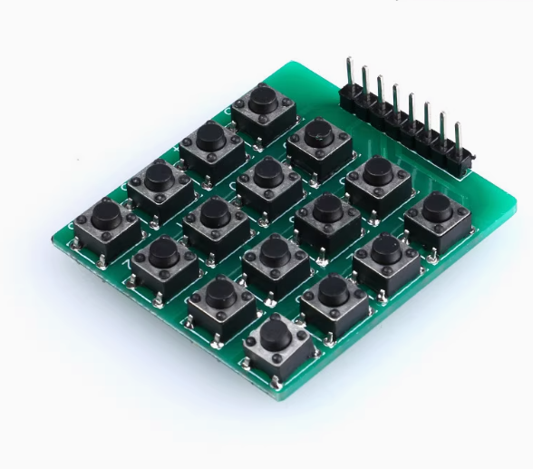
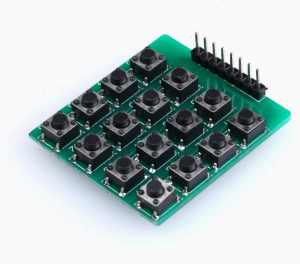
The 4×4 Matrix Membrane Keypad is a compact and durable input device featuring 16 tactile buttons arranged in a 4×4 grid. It is specifically designed to serve as a user-friendly interface for microcontroller-based projects, offering a simple and efficient way to input data, navigate menus, or control various functions in your embedded systems . The membrane construction is thin, lightweight, and flexible, making it easy to mount on enclosures, panels, or other surfaces .
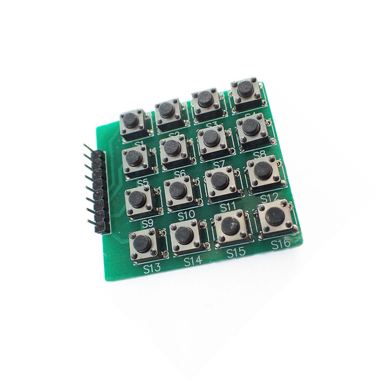
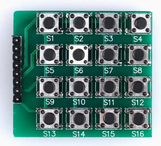
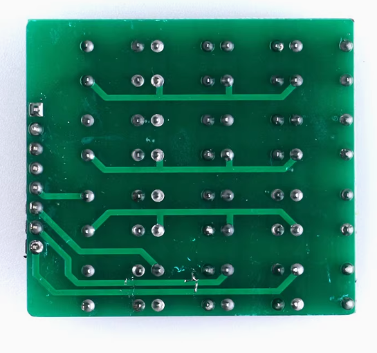
The heart of the keypad’s operation is its matrix configuration. The 16 buttons are connected to common row and column lines, creating a circuit matrix. When a button is pressed, it closes a connection between a specific row and column. This matrix structure requires only 8 general-purpose input/output (GPIO) pins on your microcontroller to read all 16 keys (4 pins for rows and 4 pins for columns), significantly conserving your controller’s valuable I/O resources . The default printed labels include the digits 0-9, letters A-D, and the * and # symbols .
Whether you are building a PIN code entry system for a security project, creating a menu-driven interface for an automation system, designing a custom calculator, or needing a robust control panel for your robotics project, this 4×4 matrix keypad module provides a reliable and easy-to-integrate solution for direct human-to-machine interaction.
Key Features
-
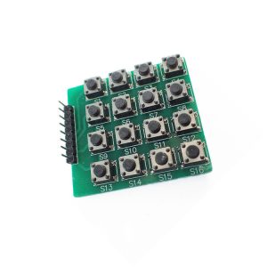
16-Button Matrix Layout: A 4×4 grid of tactile buttons providing 16 distinct inputs, including numbers 0-9, letters A, B, C, D, and symbols *, # .
-
Efficient 8‑Pin Interface: Uses only 8 pins (4 rows, 4 columns) to scan all 16 buttons, saving precious GPIO resources on your microcontroller .
-
Flexible & Durable Membrane Construction: The thin, lightweight design (approximately 1mm thick) can be mounted on uneven surfaces, and has self-adhesive backing for easy installation .
-
Wide Microcontroller Compatibility: Easily interfaces with popular platforms like Arduino, ESP32, ESP8266, Raspberry Pi, and STM32 using standard GPIO pins .
-
Extensive Software Support: Fully compatible with the popular “Keypad.h” library for Arduino, which greatly simplifies key detection and event handling .
-
Easy Mounting with Self-Adhesive Backing: The self-adhesive layer allows for quick and secure mounting on most enclosure surfaces without additional hardware .
-
Long-Lasting Durability: Rated for up to 1 million key presses and features a contact bounce time of less than 5 ms, ensuring reliable performance over long-term use .
-
Clear Tactile Feedback: Each key press provides a distinct tactile feel, confirming the input action .
Technical Specifications
Pinout & Connection Guide
The 8-pin interface is straightforward. The keypad is essentially a simple matrix. The exact order of row and column pins can vary between manufacturers, but the general concept remains the same: one set of pins controls the rows, and the other set controls the columns. The most common arrangement is the first four pins being the rows (R1-R4) and the next four being the columns (C1-C4) . However, the pin-to-button mapping in the software is easily reconfigurable.
Wiring to Arduino Uno
This is a standard wiring example. You can change the pin numbers as needed by modifying the code.
Usage Guide
1. Hardware Setup
Connecting the membrane keypad is simple, but ensuring a reliable connection is critical. The 8-pin connector (2.54mm pitch) is designed to plug directly into a breadboard or a standard female header .
-
Place Keypad: Position the keypad on a flat, clean surface near your development board.
-
Peel Protective Film: If your keypad has a protective film on the adhesive backing, remove it.
-
Connect Wires: Insert the 8-pin connector into a breadboard, or use female-to-female jumper wires to connect the keypad pins to the digital I/O pins on your microcontroller as defined in your code . Ensure the connections are firm to prevent intermittent contact.
2. Software Setup (Arduino IDE)
The recommended way to interface with a 4×4 matrix keypad is by using the “Keypad” library, which handles all the low-level pin scanning and debouncing for you.
Step 1: Install the Keypad Library
-
Open the Arduino IDE.
-
Go to Sketch → Include Library → Manage Libraries.
-
In the search bar, type “Keypad” .
-
Look for the library called “Keypad” by Mark Stanley, Alexander Brevig. Click Install .
Step 2: Basic Test Sketch
This sketch will print the key you press to the Arduino IDE’s Serial Monitor.
#include <Keypad.h>
const byte ROWS = 4;
const byte COLS = 4;
char keys[ROWS][COLS] = {
{'1','2','3','A'},
{'4','5','6','B'},
{'7','8','9','C'},
{'*','0','#','D'}
};
byte rowPins[ROWS] = {9, 8, 7, 6};
byte colPins[COLS] = {5, 4, 3, 2};
Keypad keypad = Keypad(makeKeymap(keys), rowPins, colPins, ROWS, COLS);
void setup() {
Serial.begin(9600);
Serial.println("4x4 Keypad is ready. Press any key...");
}
void loop() {
char key = keypad.getKey();
if (key) {
Serial.println(key);
}
}
Step 3: Using the Key in Your Project
Once you have successfully read the character of the pressed key, your code can branch to perform different actions based on the input. For example:
void checkForKeypadInput() {
char key = keypad.getKey();
switch(key) {
case '1':
break;
case '2':
break;
case '*':
break;
}
}
How the Matrix Scanning Works
You don’t need to code this, but understanding it helps with troubleshooting. The microcontroller scans the keypad by sequentially setting each row pin HIGH and reading the state of all the column pins. If no button is pressed, all column pins will read LOW. When a button is pressed, it connects its row and column, creating a circuit. The microcontroller detects which column is HIGH while a specific row is active, and from that, it can determine exactly which button was pressed . This scanning happens very quickly, allowing for near-instantaneous detection .
Debouncing
Mechanical switches “bounce” when pressed, causing the electrical signal to fluctuate rapidly for a very short time . The “Keypad” library has built-in debouncing logic, which ignores these false signals and ensures you only register a single, clean press for each button push .
Q: How many pins does this keypad use, and why?
It uses 8 pins, which correspond to the 4 rows and 4 columns of the button matrix. This is what allows you to read 16 individual buttons with just 8 GPIO pins.
Q: What should I do if my keypad isn't working or prints the wrong keys?
This is often a wiring or pin definition issue. First, double-check that your physical wiring matches the rowPins and colPins arrays in your code . Also, ensure the keys[][] character map accurately reflects the layout of your specific keypad.
Q: Can I change the characters the keypad outputs?
Yes, absolutely. The keys 2D array in the code defines which character is returned for each button. You can modify these to any character, word, or value you need for your project
Q: Is this a hard-button keypad or a soft membrane one?
This module uses a thin, flexible membrane construction. It is not a hard plastic button keypad, but it is durable and rated for up to one million presses .
Q: What does the 'Keypad' library do?
The Keypad library simplifies the process by handling the complex tasks of scanning the 8-pin matrix, debouncing the button presses, and translating raw electrical signals into clean, reliable character outputs .
Q: Can these keypads be used outdoors?
The operating temperature range is -20°C to +40°C and they are not waterproof . For outdoor use, they would need to be protected inside a weatherproof enclosure.
Q: Can I press multiple keys at the same time?
The standard matrix scanning technique can sometimes have difficulty with simultaneous presses. The “Keypad” library can handle basic combinations, but for complex multi-key inputs, a more advanced matrix (like one with diodes) is required.
Q: Does this keypad work with a Raspberry Pi?
Yes, it works with any device that has GPIO pins. You would need to install a Python library (e.g., pad4pi or keypad) and wire the 8 pins to the Pi’s GPIO .
Q: How can I use interrupt-driven key detection instead of polling?
The keypad.getKey() function relies on polling within the loop(). For time-sensitive applications, you can implement interrupts by wiring the keypad’s output to a GPIO pin capable of generating interrupts, though this method is more complex. Most projects work perfectly with the standard getKey() polling method .
Q: Why is my keypad registering random double presses?
While the library has debouncing, you might need to adjust it if the bounce time is longer than the default. You can increase the debounce time in the library’s settings to make it more tolerant, or ensure your power supply is stable to prevent noise.