Product Overview
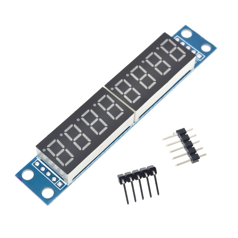
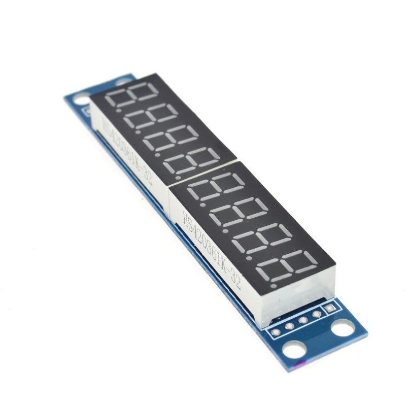
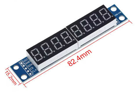
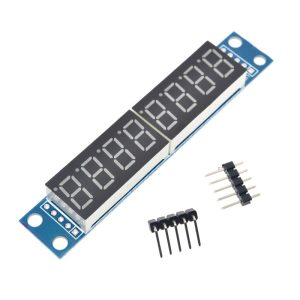
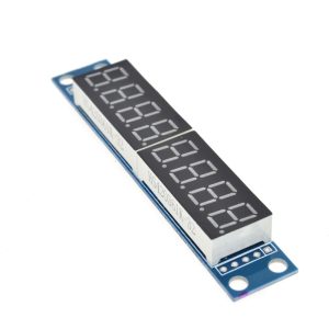
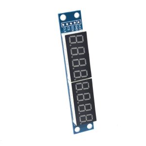
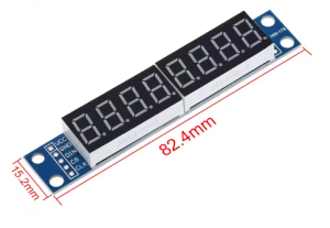
The MAX7219 8-Bit Digital Tube Display Module is a complete, ready-to-use solution for driving eight 7-segment LED displays. Based on the industry-standard MAX7219 driver IC from Maxim Integrated (now Analog Devices), this module allows you to control up to 8 digits using only 3 I/O pins from your microcontroller – a dramatic reduction from the 16+ pins typically required for direct drive .
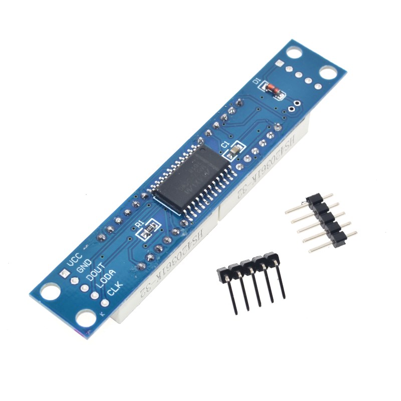
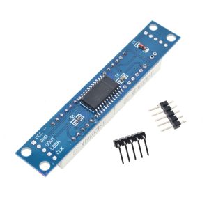
The MAX7219 is a compact, serial input/output common-cathode display driver that interfaces microprocessors to 7-segment numeric LED displays of up to 8 digits, bar-graph displays, or 64 individual LEDs . On-chip features include a BCD code-B decoder, multiplex scan circuitry, segment and digit drivers, and an 8×8 static RAM that stores each digit . Only one external resistor is required to set the segment current for all LEDs.
This module solves the common problem of limited I/O pins. With just three connections – DIN (Data In), CLK (Clock), and CS/LOAD (Chip Select) – you can display numbers, letters, and custom characters across all eight digits. The module supports cascading (daisy-chaining) , allowing you to connect multiple modules in series to drive 16, 24, or more digits using the same three control pins .
Whether you are building a digital clock, a temperature display, a counter, a scoreboard, or any project requiring numeric readout, this MAX7219 8-bit LED tube module provides a simple, efficient, and robust solution .
Key Features
-
8-Digit LED Display: Drives up to eight 7-segment LED digits (also supports 8×8 LED matrices and bar-graph displays) .
-
3-Wire Serial Interface: Uses only 3 I/O pins (DIN, CLK, LOAD/CS) to control all 8 digits, freeing up valuable microcontroller pins .
-
High-Speed 10MHz Interface: Enables fast data transmission and real-time display updates without noticeable lag .
-
On-Chip BCD Decoder: Built-in Code B decoder simplifies displaying digits 0-9, with the option to bypass for custom character control .
-
8×8 Static RAM: Internal memory stores each digit’s data, allowing independent updates without rewriting the entire display .
-
16-Step Digital Brightness Control: Software-adjustable brightness from 1/32 to 31/32 of peak current (16 levels) .
-
150µA Low-Power Shutdown Mode: Reduces power consumption when the display is not needed, while retaining data .
-
Display Test Mode: One command lights all segments for quick functionality testing .
-
Cascadable Design: Multiple modules can be daisy-chained to drive 16, 24, or more digits using the same 3 control pins .
-
Wide Operating Voltage: Compatible with 5V systems (Arduino) and 3.3V systems with level shifters .
-
Scan Limit Register: Configurable to display 1 to 8 digits, saving power when fewer digits are needed .
Technical Specifications
Pinout & Interface Guide
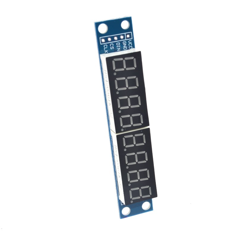
The module features a standard 5-pin interface (2.54mm pitch) for easy connection to microcontrollers .
Cascading Multiple Modules
To connect multiple modules in series (daisy chain):
All modules share the same CS, CLK, VCC, and GND lines . The data is shifted through the chain – first to the farthest module, then back to the closest .
Usage Guide
Hardware Setup
-
Connect VCC to 5V on your Arduino (or appropriate supply)
-
Connect GND to GND
-
Connect DIN to digital pin 11 (or any available pin)
-
Connect CS/LOAD to digital pin 10 (or any available pin)
-
Connect CLK to digital pin 13 (or any available pin)
For 3.3V microcontrollers (ESP32, ESP8266), a logic level converter is recommended as the MAX7219 is designed for 5V logic .
Software Setup (Arduino IDE)
The easiest way to control this module is using the LedControl library by Eberhard Fahle.
Step 1: Install the LedControl Library
-
Open Arduino IDE → Sketch → Include Library → Manage Libraries
-
Search for “LedControl”
-
Find the library by Eberhard Fahle and click Install
Step 2: Basic Test Sketch
#include <LedControl.h>
LedControl lc = LedControl(11, 13, 10, 1);
void setup() {
lc.shutdown(0, false);
lc.setIntensity(0, 8);
lc.clearDisplay(0);
for (int i = 0; i < 8; i++) {
lc.setDigit(0, i, i, false);
delay(500);
}
}
void loop() {
for (int i = 0; i <= 99999999; i++) {
lc.setNumber(0, i);
delay(10);
}
}
Step 3: Displaying Custom Characters (No-Decode Mode)
For custom characters (like letters or symbols), you can bypass the BCD decoder:
lc.setDigit(0, 0, 0x7E, true);
Understanding the Registers
The MAX7219 is controlled by writing 16-bit commands: 8 bits for the register address and 8 bits for the data .
Example: Displaying a Floating Point Number
To display a number with a decimal point, you need to control the DP segment manually or use the appropriate data byte. In the LedControl library, the setDigit() function’s fourth parameter is a boolean for the decimal point:
lc.setDigit(0, 2, 5, true);
Power Supply Considerations
The module’s current consumption varies significantly with brightness and the number of segments lit:
-
Minimum (all segments off): ~8mA
-
Typical (normal brightness, all segments on): ~80-150mA
-
Maximum (full brightness, all segments lit): ~330mA
Ensure your power supply can deliver adequate current, especially when cascading multiple modules. For battery-powered projects, consider using the shutdown mode when the display is not needed .
Q: How many I/O pins does this module require?
This module requires only 3 I/O pins from your microcontroller: DIN (data), CLK (clock), and CS/LOAD (chip select). This is a dramatic reduction from the 16+ pins needed to directly drive 8 seven-segment displays.
Q: Can I use this module with 3.3V microcontrollers like ESP32 or ESP8266?
The MAX7219 is designed for 5V logic. While some users report success with 3.3V, it is recommended to use a logic level converter between your 3.3V microcontroller and the 5V module for reliable operation .
Q: How do I cascade multiple modules?
Connect the DOUT pin of the first module to the DIN pin of the second module. All other pins (VCC, GND, CS, CLK) are connected in parallel. Update the device count in your code (e.g., LedControl lc(11, 13, 10, 2) for two modules).
Q: My display is not showing anything. What should I check?
Common issues:
-
Ensure the module is not in shutdown mode (lc.shutdown(0, false))
-
Check that the scan limit register is set correctly (lc.setScanLimit(0, 7) for 8 digits)
-
Verify that the brightness is not set to zero (lc.setIntensity(0, 8))
-
Double-check wiring – especially the CS/LOAD pin which latches the data
Q: Can I display letters on this module?
Yes, the built-in BCD decoder can display digits 0-9 and certain letters (E, H, L, P, and blank). For custom characters, disable the BCD decoder for that digit and control the segments directly using segment data bytes .
Q: How do I control the brightness?
Use the lc.setIntensity(0, value) function where value is 0 (minimum) to 15 (maximum). The underlying register (0x0A) controls a PWM that scales the average segment current .
Q: What is the difference between MAX7219 and MAX7221?
Both are functionally similar, but the MAX7221 includes slew-rate limited segment drivers for reduced EMI and is fully SPI-compatible . Most low-cost modules use the MAX7219. Both work with the same software and wiring.
Q: How do I display a number with leading zeros suppressed?
You can use the lc.setDigit() function conditionally, or write a custom function that checks if higher digits are zero. The LedControl library’s setNumber() function typically does not suppress leading zeros automatically.
Q: Does this module have built-in current-limiting resistors?
The MAX7219 uses a single external resistor (RSET) between the ISET pin and VCC to set the peak segment current for all segments . On ready-made modules, this resistor is already populated.
Q: What is the purpose of the "Display Test" mode?
The display test mode (register 0x0F) lights up all segments on all digits when set to 0x01. This is useful for verifying that all segments are functioning properly .