Product Overview
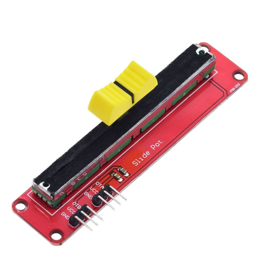
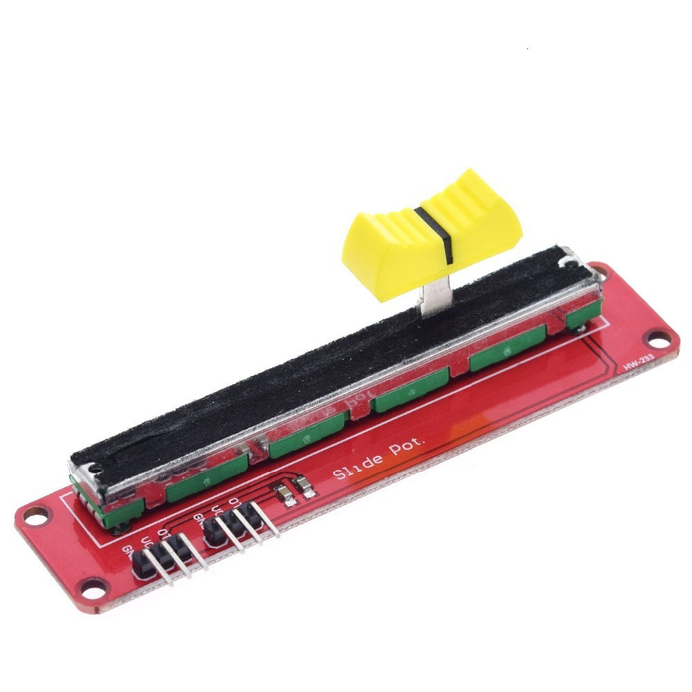
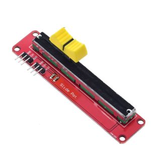
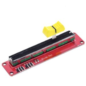
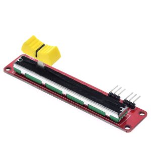
The B10K Adjustable Slide Potentiometer Module is a compact, user-friendly analog input device designed to provide smooth, linear control over voltage levels in your electronic projects. The “B10K” designation indicates a 10,000 ohm (10kΩ) resistance with a linear taper , meaning the resistance changes evenly across the entire sliding range, giving you predictable and proportional control.
This module converts the mechanical position of the slider into a variable voltage output, making it an essential component for applications requiring manual adjustment of parameters. Whether you need to control the volume of an audio amplifier, adjust the brightness of an LED, fine-tune a power supply, or provide user input for a microcontroller-based project, this slide potentiometer module offers a reliable and intuitive solution.
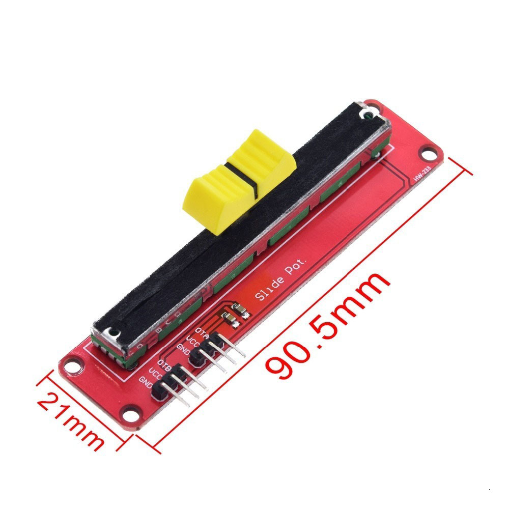
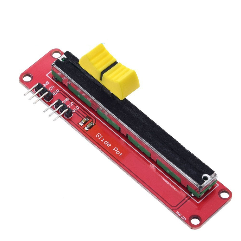
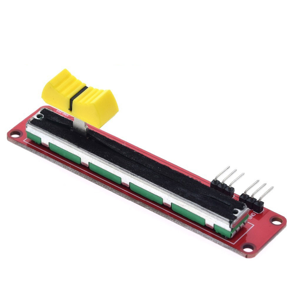
The module is designed for easy integration with development platforms like Arduino, ESP32, Raspberry Pi, and STM32. It features a simple 3-pin interface (VCC, GND, SIG), where the signal pin outputs an analog voltage that varies from 0V to the supply voltage (typically 3.3V or 5V) as you slide the control . This analog output can be read by a microcontroller’s Analog-to-Digital Converter (ADC) to capture precise positional data.
The slide mechanism provides smooth, continuous travel with excellent tactile feedback , making it ideal for mixing consoles, lighting desks, DJ equipment, test instruments, and DIY electronic control panels. Unlike rotary potentiometers, the linear sliding action offers a visual indication of the current setting, which is particularly useful in applications where at-a-glance status is valuable.
Key Features
-
10kΩ Linear Resistance (B-Taper): Provides smooth, predictable, and proportional control throughout the entire sliding range. The “B” taper means the resistance changes linearly with slider position, giving equal sensitivity across the entire travel .
-
Low Power Consumption: The module itself consumes very little power (typically the wiper current is negligible), making it suitable for battery-powered projects and portable devices.
-
Simple 3-Pin Interface: Standard pinout with VCC (power), GND (ground), and SIG (analog signal output) for easy connection to microcontrollers and development boards.
-
Long Mechanical Life: Rated for up to 15,000 operating cycles (typical specification), ensuring long-term reliability for frequently adjusted controls .
-
Compact & Versatile: Available in various slide travel lengths (typically 30mm, 35mm, 45mm, 60mm, or 100mm) to suit different panel sizes and user interface requirements .
-
Low Output Noise: Designed for clean signal output with minimal electrical noise (slide noise typically less than 47mV), suitable for audio and precision analog applications .
-
Excellent Linearity: Provides accurate resistance tracking across the slide length, ensuring consistent and repeatable performance.
-
Easy Mounting: Designed for panel mounting with mounting holes and shaft nut, facilitating secure installation on instrument panels, mixers, or project enclosures .
Technical Specifications
Pinout & Connection Guide
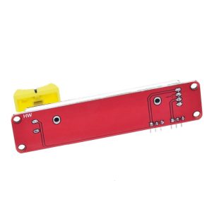
The slide potentiometer typically has three terminals, arranged as shown in the diagram:
Note: The pin numbering convention may vary (1-2-3 vs. 3-2-1). Always verify the orientation of your specific model. Some units may have “A”, “B”, and “C” label designations.
Wiring Diagram (Arduino UNO)
Usage Guide
Basic Operation Principle
The slide potentiometer acts as a variable voltage divider. When you connect the fixed ends across a voltage supply (e.g., 5V and GND), the center wiper will output a voltage that is proportional to its position. At one end, the output will be approximately 0V; at the other end, it will be approximately VCC. As you slide the control, the output voltage changes linearly, providing a direct analog representation of the slider’s physical position .
Example: Reading Analog Values with Arduino
This code reads the voltage from the potentiometer and prints the raw ADC value (0-1023) to the Serial Monitor .
B10K Slide Potentiometer Read Example
*/
int potPin = A0;
int rawValue = 0;
void setup() {
Serial.begin(9600);
pinMode(potPin, INPUT);
}
void loop() {
rawValue = analogRead(potPin);
Serial.print("Potentiometer Value: ");
Serial.println(rawValue);
float voltage = (rawValue / 1023.0) * 5.0;
Serial.print("Voltage: ");
Serial.print(voltage);
Serial.println(" V");
delay(100);
}
Practical Applications
Audio Volume Control: Use the potentiometer as a passive attenuator in audio circuits to control volume or tone . For better performance, consider adding a buffer amplifier.
LED Brightness Control: Connect the wiper to a microcontroller’s ADC, and use the mapped value to set the duty cycle of a PWM signal controlling an LED, achieving smooth brightness adjustment .
Power Supply Adjustment: In DIY power supply projects, use the potentiometer as a feedback voltage divider to set the output voltage of a variable regulator.
Lighting Control: Perfect for controlling LED strip brightness or DMX512 lighting desk applications, where smooth fader control provides precise intensity adjustment .
User Interface Control: Use the fader to send analog control signals to a microcontroller, which can then be used to control software parameters, graphic equalizers, or any other user-adjustable setting.
Q: What does "B10K" mean?
The “B” indicates a linear taper, meaning the resistance changes linearly with the slider position. “10K” means the total resistance is 10,000 ohms (10 kΩ) . Linear taper is ideal for voltage divider applications because the output voltage is proportional to the slider position.
Q: How is a slide potentiometer different from a rotary potentiometer?
Both are variable resistors; the slide pot uses a linear sliding motion to adjust the resistance, while a rotary pot uses a circular rotation. Slide pots are often preferred for applications requiring a visual indication of the setting (like in audio mixers) and are easier to use in certain panel layouts. They also allow for easy ganging of multiple units.
Q: Can I connect this directly to an Arduino or ESP32?
Yes, you can connect it directly to a 5V or 3.3V supply (depending on your board). The wiper outputs a variable voltage that can be safely read by a microcontroller’s analog input (ADC) pin . For 3.3V boards, use 3.3V power for optimal range.
Q: How do I wire the potentiometer to get a varying voltage?
Connect the two outer terminals to VCC and GND, and the middle terminal (wiper) to your analog input pin . When you slide the control, the voltage on the wiper will vary smoothly between 0V and VCC.
Q: What is the typical slide travel length?
Slide travel lengths vary by model, common lengths include 30mm, 35mm, 45mm, 60mm, and 100mm . Choose the length based on your panel size and required resolution.
Q: The analog readings are jumping around. How do I fix this?
This is often due to electrical noise. You can add a small capacitor (e.g., 0.1µF) between the wiper (SIG) and GND to filter out high-frequency noise. Also, check that your power supply is stable and your wiring is secure.
Q: What is the power rating of this potentiometer?
The power rating is typically between 0.05W and 0.5W . This means it is suitable only for low-power signal applications, not for directly controlling high-power devices like motors or heaters. For power control, use a transistor or a power module.
Q: Can I use this for audio applications like a volume control?
Yes, slide potentiometers are widely used in audio mixers and music equipment for volume, pan, and EQ controls . For audio, you can wire it as a voltage divider to create a passive attenuator.
Q: How long does this potentiometer last?
Typical slide potentiometers have a mechanical life rating of over 15,000 operating cycles . This is adequate for frequent use in consumer electronics and test equipment.
Q: What is the difference between linear and logarithmic (audio) taper?
Linear taper (B-taper) changes resistance evenly across the slide, making it ideal for voltage dividers and tone controls. Logarithmic (audio) taper (A-taper) changes resistance logarithmically, matching the non-linear sensitivity of the human ear, and is preferred for volume controls .