Product Overview
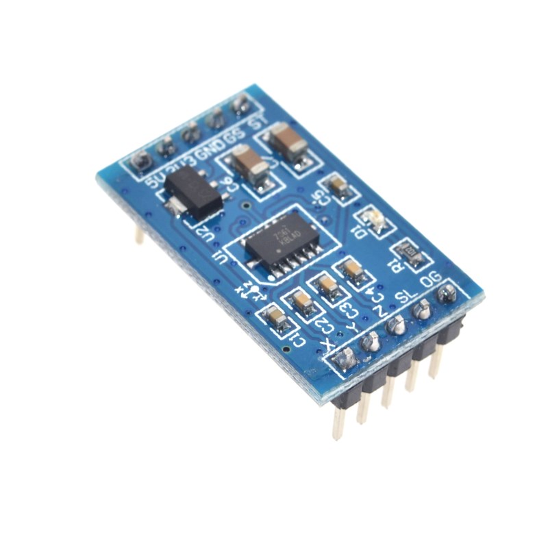
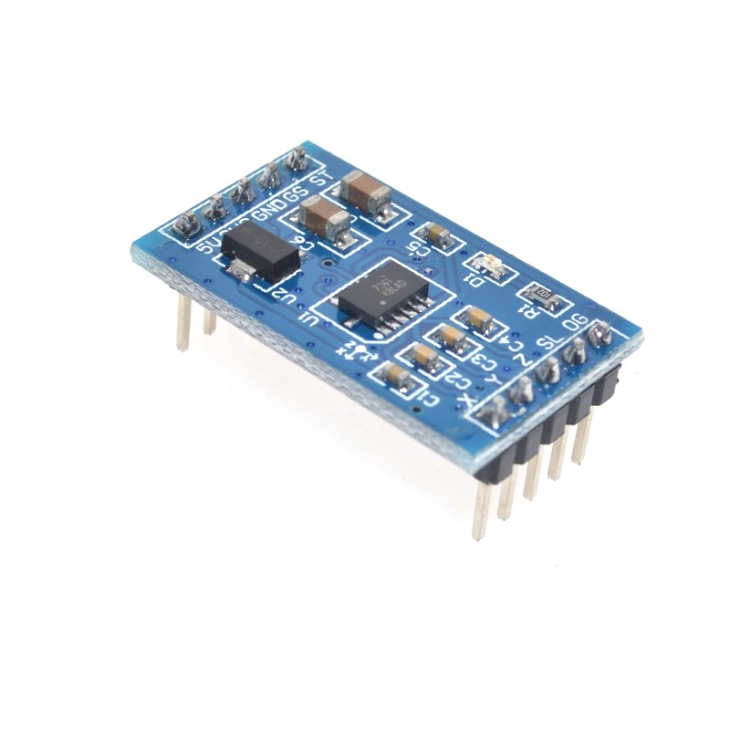
The MMA7361 Angle Acceleration Sensor Module is a high-performance, low-power triple-axis accelerometer designed to measure acceleration forces in three dimensions: X, Y, and Z. As the recommended replacement for the discontinued MMA7260 module, this sensor provides a seamless upgrade path for existing projects while offering superior stability and power efficiency .
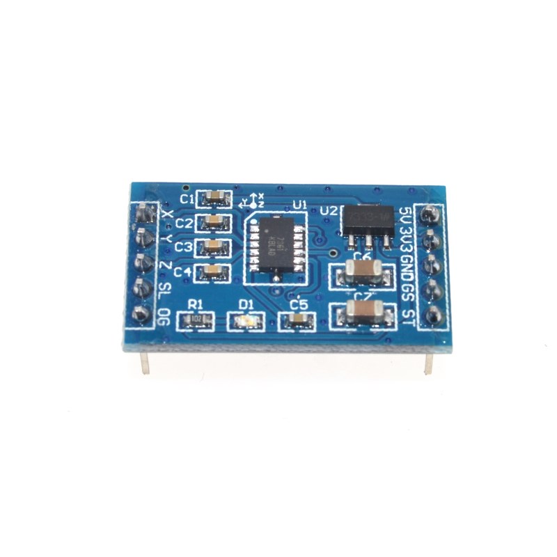
At its core is the Freescale MMA7361L MEMS accelerometer—a low-power, low-profile capacitive micromachined sensor that converts motion and tilt into analog voltage outputs. Each axis (X, Y, Z) outputs a voltage proportional to the acceleration experienced on that axis, allowing your microcontroller to read the sensor data via standard analog input pins .
The sensor features selectable sensitivity (±1.5g or ±6g) , enabling you to choose between high sensitivity for precise tilt measurements or a wider range for detecting stronger acceleration forces . An onboard voltage regulator supports both 3.3V and 5V systems, making the module compatible with Arduino, ESP32, STM32, and Raspberry Pi .
With an ultra-low operating current of 400µA (3µA in sleep mode), the MMA7361 is ideal for battery-powered applications such as wearable devices, wireless sensors, and portable instruments . Built-in features include signal conditioning, low-pass filtering, temperature compensation, and 0g-detect (freefall detection) —all factory-calibrated, requiring no external components .
Key Features
-
Triple-Axis Acceleration Measurement: Measures acceleration on X, Y, and Z axes simultaneously .
-
Selectable Sensitivity (2 Ranges): Choose between ±1.5g (high sensitivity, 800 mV/g) and ±6g (wide range) via a DIP switch or MCU-controlled pin .
-
Analog Voltage Output: Each axis provides a ratiometric analog voltage output (0–VCC), compatible with any microcontroller’s ADC .
-
Wide Power Supply Range: Operates from 3.3V to 8V DC; onboard regulator supports both 3.3V and 5V logic systems .
-
Ultra-Low Power Consumption: Consumes only 400µA in active mode and 3µA in sleep mode, ideal for battery-powered devices .
-
Built-in Low-Pass Filter: Internal signal conditioning with a 1-pole low-pass filter provides clean, stable output .
-
0g-Detect (Freefall Detection): Digital output pin indicates when the device is in freefall (0g on all axes) .
-
Self-Test Function: Verifies sensor operation through an electrostatic force applied to the sensing element .
-
Temperature Compensation: Maintains accuracy across the -40°C to +85°C operating range .
-
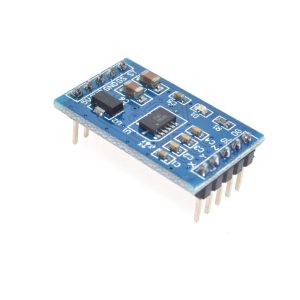
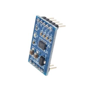
Compact Breakout Board: Small 2.54mm pin spacing, gold-plated pads for easy breadboard or PCB integration .
Technical Specifications
Pinout & Interface Guide
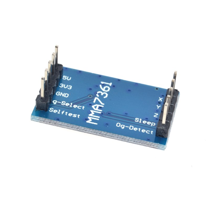
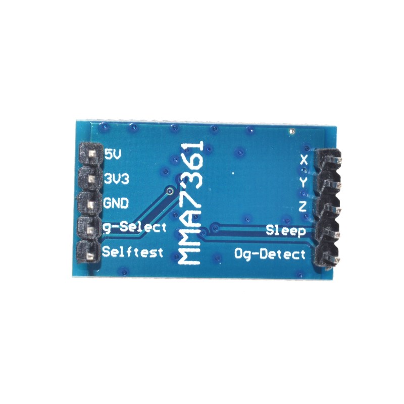
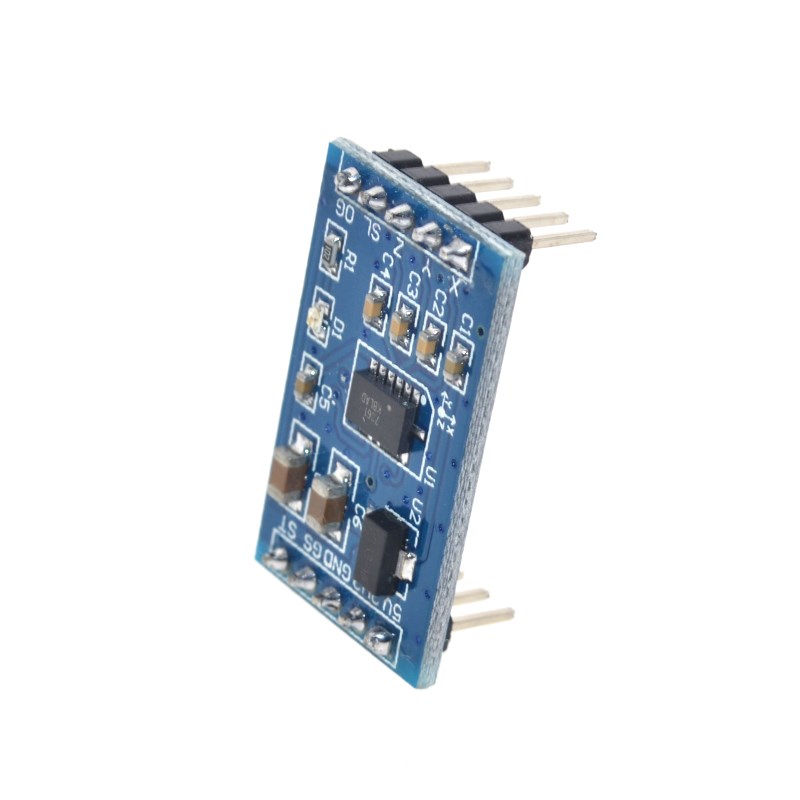
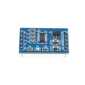
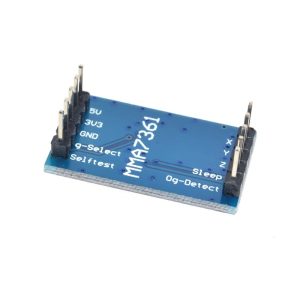
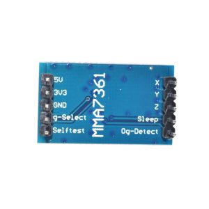
The breakout board features a 10-pin header (2.54mm pitch) with clearly labeled functions. Pin numbering may vary slightly between manufacturers—always verify the silkscreen on your specific board .
Usage Guide
Wiring Instructions
Basic Connection (Arduino Uno) :
Software Setup (Arduino IDE)
Step 1: Read Analog Values
const int xPin = A0;
const int yPin = A1;
const int zPin = A2;
void setup() {
Serial.begin(9600);
pinMode(xPin, INPUT);
pinMode(yPin, INPUT);
pinMode(zPin, INPUT);
}
void loop() {
int xValue = analogRead(xPin);
int yValue = analogRead(yPin);
int zValue = analogRead(zPin);
Serial.print("X: "); Serial.print(xValue);
Serial.print(" | Y: "); Serial.print(yValue);
Serial.print(" | Z: "); Serial.println(zValue);
delay(100);
}
Step 2: Convert ADC Values to Acceleration
The output is ratiometric—the zero-g point is at VCC/2 (approximately 512 at 5V). Use this formula to calculate g-force:
float convertToG(int adcValue, float sensitivity) {
float voltage = (adcValue / 1023.0) * 5.0;
float zeroG = 2.5;
return (voltage - zeroG) / sensitivity;
}
float gForce = convertToG(analogRead(xPin), 0.8);
Typical sensor orientation yields:
-
Flat (face up): X ≈ 512, Y ≈ 512, Z ≈ 512–640 (≈1g gravity)
-
On its side (X down): X ≈ 512–640, Y ≈ 512, Z ≈ 512
Selecting Sensitivity (g-select)
Control with Arduino:
pinMode(gSelectPin, OUTPUT);
digitalWrite(gSelectPin, LOW);
digitalWrite(gSelectPin, HIGH);
Power Management
-
Active Mode: Keep the Sleep pin HIGH (or connected to VCC)
-
Sleep Mode: Pull the Sleep pin LOW. The sensor will draw only 3µA, preserving battery power .
Self-Test Feature
Activating self-test (pull SelfTest pin HIGH) applies an electrostatic force to the sensing element, creating a predictable deflection. This verifies the sensor is functioning correctly .
Q: What is the difference between MMA7361 and MMA7260?
The MMA7361 is the recommended direct replacement for the discontinued MMA7260. It offers the same pinout and functionality with improved power efficiency (400µA vs higher consumption) and enhanced temperature stability . Both support ±1.5g/±6g selectable ranges and analog outputs
Q: Can I use this module with a 3.3V microcontroller (ESP32, ESP8266, STM32)?
Yes. The module accepts both 3.3V and 5V power. For 3.3V operation, connect the 3V3 pin instead of the 5V pin. The analog outputs will range from 0V to 3.3V, matching the ADC input range of these microcontrollers .
Q: How does the 0g-detect pin work?
The 0g-detect pin outputs a digital HIGH signal when the sensor is in linear freefall (all three axes experience near-zero acceleration). This is used in hard drive protection and other fall-detection applications .
Q: Why are my analog readings around 512 when the sensor is stationary?
This is the zero-g offset. When no acceleration is applied (excluding gravity), the output sits at VCC/2. For 5V power, this is approximately 2.5V (ADC value ~512). Gravity adds about 1g (~205 ADC counts), so readings increase or decrease depending on orientation.
Q: What are the typical applications for this sensor?
Common applications include:
-
Robotics: Tilt detection for balancing robots and humanoid stability
-
Gaming: Motion-sensing controllers and gesture recognition
-
IoT: Fall detection for elderly monitoring and equipment protection
-
Navigation: E-compass tilt compensation
Q: How can I reduce noise in the analog readings?
To obtain stable readings:
-
Add a 0.1µF capacitor between each analog output (X, Y, Z) and GND to implement the recommended low-pass filter
-
Use the Arduino’s analogReference(DEFAULT) setting
-
Average multiple readings (e.g., take 10 samples and average)
Q: The module becomes hot during operation. Is this normal?
The MMA7361 itself draws only 400µA and should not become hot. If the module is warm, verify your power supply voltage and check for short circuits. The onboard RT9161 regulator may generate slight heat but should not be too hot to touch .
Q: What does the self-test function do?
The self-test pin, when driven HIGH, applies an electrostatic force to the internal sensing element, simulating acceleration. This verifies the mechanical and electrical integrity of the sensor without physically moving it .
Q: How do I choose between ±1.5g and ±6g ranges?
Use ±1.5g (800mV/g) for tilt measurement, angle detection, and applications requiring high sensitivity. Use ±6g (206mV/g) for detecting motion shocks, impacts, or any movement exceeding 1.5g (e.g., vibration monitoring) .
Q: The sensor's output is unaffected when tilted. What is wrong?
Possible issues:
-
Verify the Sleep pin is HIGH (active mode)
-
Ensure the g-select pin is connected to GND or VCC (not floating)
-
Check power and ground connections
-
Confirm you are reading the correct analog pins