Product Overview
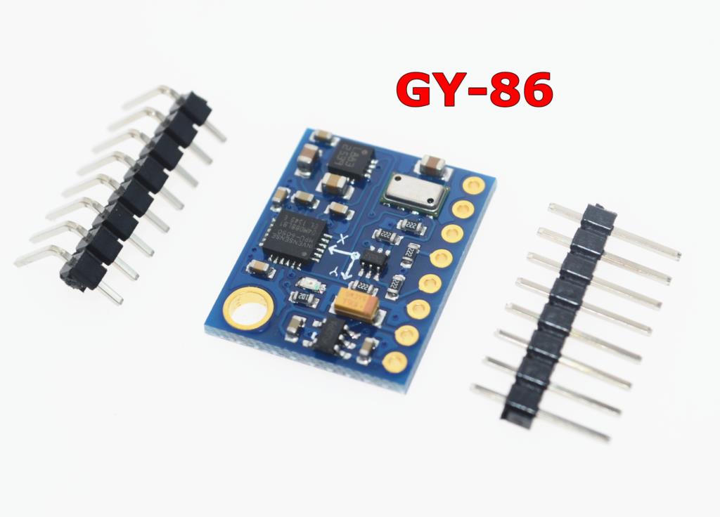
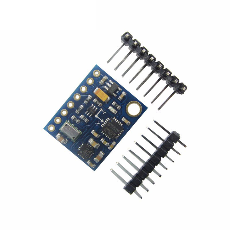
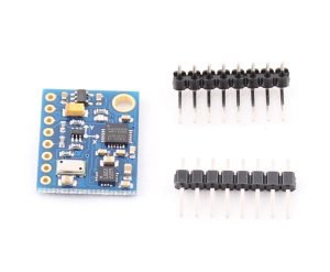
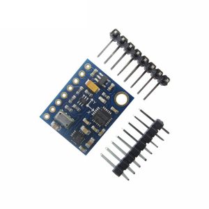
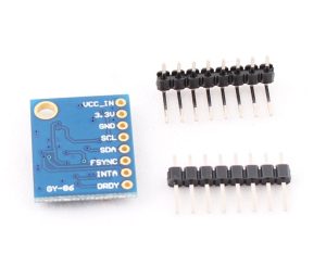
The GY-86 10DOF Flight Control Sensor Module is a powerful, all‑in‑one motion‑tracking board that integrates four high‑performance MEMS sensors into a single compact package. Combining a 3‑axis gyroscope, 3‑axis accelerometer, 3‑axis magnetometer, and a high‑resolution barometer, this module provides a complete 10‑degree‑of‑freedom (10DOF) sensing solution for advanced motion and orientation applications .
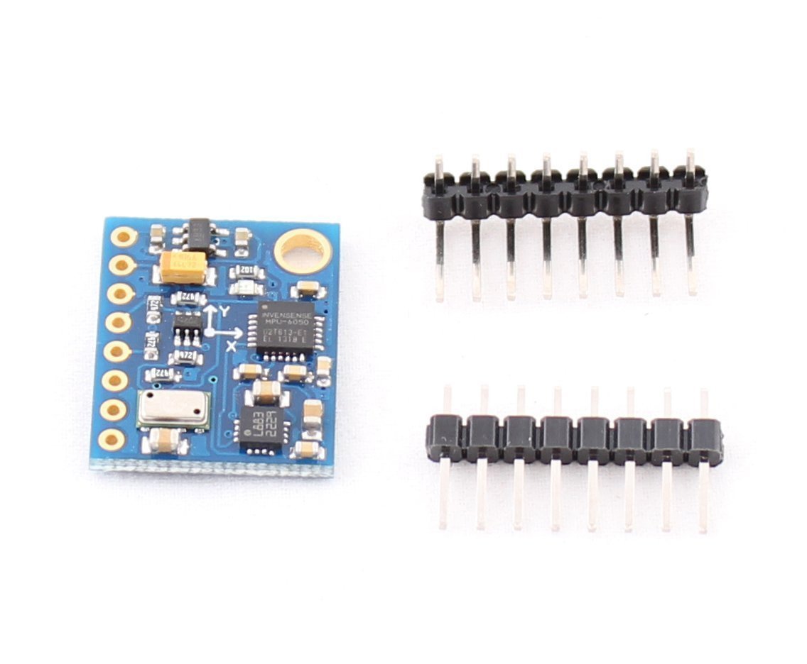
Built around the popular MPU6050 (which integrates both gyroscope and accelerometer), the HMC5883L magnetometer, and the MS5611 barometer, the GY-86 is widely used in drones (UAVs), quadcopters, robotics, head‑tracking systems, and inertial navigation. It is also the sensor core for many MWC (MultiWii Copter) flight controllers, making it a favorite among drone enthusiasts and professional developers alike .
All sensors communicate via a shared I2C bus, requiring only two data lines (SDA and SCL) to connect to your microcontroller. The module operates on 3V to 5V power and includes onboard logic‑level conversion (LLC), making it directly compatible with both 3.3V and 5V systems such as Arduino, ESP32, ESP8266, Raspberry Pi, and STM32 .
Key Features
-
10‑Degree‑of‑Freedom (10DOF) Sensing: Combines 3‑axis gyroscope (angular velocity), 3‑axis accelerometer (linear acceleration/gravity), 3‑axis magnetometer (magnetic heading), and 1‑axis barometric pressure (altitude) .
-
MPU6050 Integrated Gyroscope + Accelerometer: Digital motion processor (DMP) capable of processing complex motion algorithms onboard. User‑programmable gyroscope ranges: ±250, ±500, ±1000, ±2000°/s. Accelerometer ranges: ±2g, ±4g, ±8g, ±16g .
-
HMC5883L 3‑Axis Magnetometer: 12‑bit ADC with ±8 Gauss range, 1°–2° heading accuracy, and integrated degaussing straps for resetting the sensor .
-
MS5611 High‑Resolution Barometer: 24‑bit ΔΣ ADC with factory‑calibrated coefficients. Pressure range: 10 to 1200 mbar, altitude resolution down to 10 cm (0.1 meters) .
-
Single I2C Interface: All sensors share the same I2C bus – only 2 pins (SDA, SCL) are needed to communicate with all four sensors .
-
Wide Voltage Compatibility: Operates on 3V – 5V DC with onboard LLC circuit, compatible with both 3.3V and 5V microcontrollers .
-
Compact & Lightweight: Dimensions of approximately 22mm × 17mm and very light weight, ideal for drones and portable devices .
-
Immersion Gold PCB: High‑quality PCB with gold‑plated pads for improved solderability and corrosion resistance .
Technical Specifications
Sensor Details
MPU6050 – 3‑Axis Gyroscope & 3‑Axis Accelerometer
The MPU6050 is the world’s first integrated 6‑axis motion tracking device that combines a 3‑axis gyroscope and a 3‑axis accelerometer on the same silicon die. Key features include:
-
Digital Motion Processor (DMP) : Onboard processor capable of running complex motion algorithms, offloading work from the main microcontroller.
-
16‑bit ADCs for both gyroscope and accelerometer outputs.
-
User‑programmable ranges: Gyroscope: ±250, ±500, ±1000, ±2000°/s; Accelerometer: ±2g, ±4g, ±8g, ±16g .
-
Programmable low‑pass filter for noise reduction.
HMC5883L – 3‑Axis Magnetometer (Digital Compass)
The HMC5883L measures the Earth’s magnetic field to determine absolute heading (direction). Key features include:
-
12‑bit ADC with 2 mG per LSB resolution.
-
±8 Gauss measurement range.
-
Integrated degaussing straps to reset the sensor and remove residual magnetic offset.
-
Heading accuracy of 1°–2° after calibration .
MS5611 – High‑Resolution Barometer (Altimeter)
The MS5611 is a high‑resolution altimeter sensor optimized for altitude measurement. Key features include:
-
24‑bit ΔΣ ADC for high‑precision pressure conversion.
-
Factory‑calibrated coefficients stored in internal PROM – no user calibration required.
-
Pressure range: 10 to 1200 mbar (covers altitudes from below sea level to approximately 9,000 meters).
-
Altitude resolution: Up to 10 cm (0.1 meters) .
-
Built‑in temperature sensor for accurate thermal compensation.
Pinout & Connection Guide
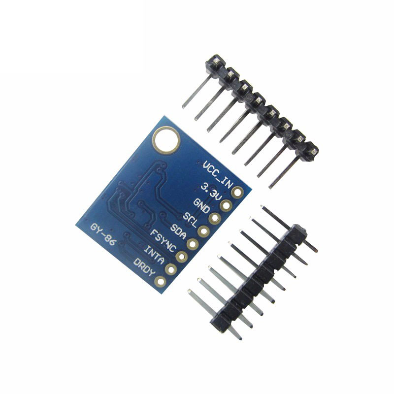
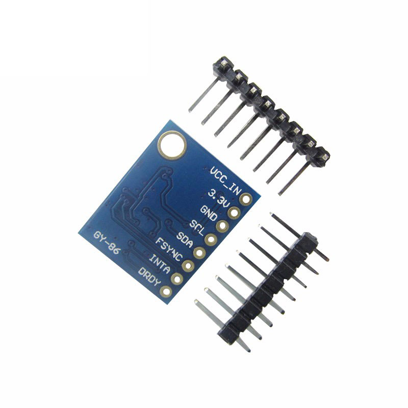
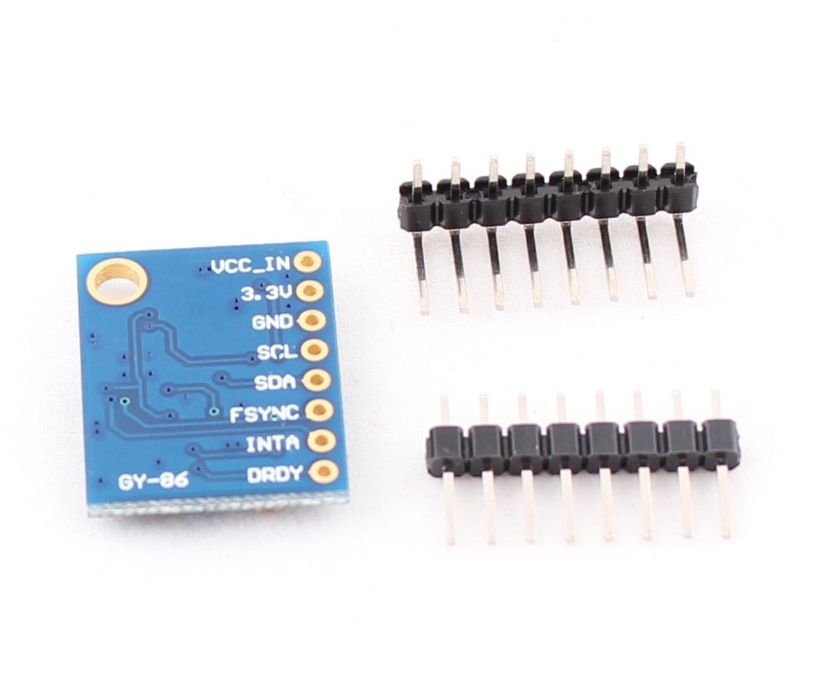
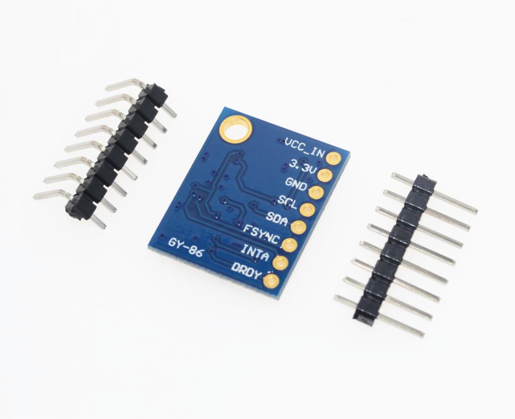
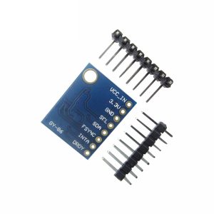
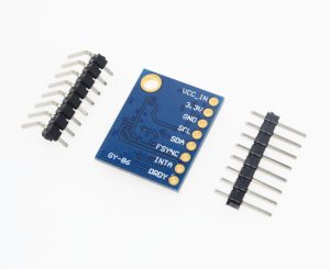
The GY-86 module features a standard 8‑pin configuration. Pin labeling may vary slightly between manufacturers; always verify the silkscreen on your specific board .
Pin Definitions
I2C Pin Mapping for Common Development Boards
Wiring Diagram (Arduino Uno)
GY-86 Module          →    Arduino Uno
─────────────────────────────────────────
VCC                   →    5V
GND                   →    GND
SCL                   →    A5 (SCL)
SDA                   →    A4 (SDA)
AD0 (optional)        →    GND (default address 0x68)
INT (optional)        →    Leave unconnected
Important Notes on I2C Bus & MPU6050 Bypass Mode
Critical: The HMC5883L magnetometer is connected internally to the auxiliary I2C bus of the MPU6050, not directly to the main I2C bus of the module . To access the magnetometer, you must configure the MPU6050 to operate in I2C bypass mode. This is done by setting the following registers :
mpu.setI2CMasterModeEnabled(false);
mpu.setI2CBypassEnabled(true);
mpu.setSleepEnabled(false);
Without these settings, you will only be able to read the MPU6050 (gyro/accel) but not the HMC5883L magnetometer. The barometer (MS5611) is accessible directly without special configuration.
Pull‑Up Resistor Requirements
The I2C bus requires pull‑up resistors on the SDA and SCL lines. Most GY-86 modules include onboard 4.7kΩ pull‑ups, but if you experience communication issues, adding external 4.7kΩ resistors can improve reliability, especially with long cables or multiple I2C devices.
Usage Guide
Software Setup (Arduino IDE)
Step 1: Install Required Libraries
The GY-86 module is supported by several libraries. The most comprehensive is Jeff Rowberg’s I2Cdevlib, which provides individual libraries for each sensor.
-
Download the libraries from: https://github.com/jrowberg/i2cdevlib
-
Copy the MPU6050, HMC5883L, and MS5611 folders to your Arduino/libraries directory
-
Restart the Arduino IDE
Step 2: MPU6050 Bypass Mode Configuration – VERY IMPORTANT!
To access the HMC5883L magnetometer, you must configure the MPU6050 to enable I2C bypass mode. Add the following lines immediately after initializing the MPU6050 :
#include <Wire.h>
#include "I2Cdev.h"
#include "MPU6050.h"
#include "HMC5883L.h"
MPU6050 mpu;
HMC5883L mag;
void setup() {
Wire.begin();
Serial.begin(115200);
mpu.initialize();
mpu.setI2CMasterModeEnabled(false);
mpu.setI2CBypassEnabled(true);
mpu.setSleepEnabled(false);
mag.initialize();
Serial.println(mpu.testConnection() ? "MPU6050 OK" : "MPU6050 ERROR");
Serial.println(mag.testConnection() ? "HMC5883L OK" : "HMC5883L ERROR");
}
Step 3: Complete Sensor Reading Example
GY-86 10DOF IMU – Complete Sensor Reading Example
Reads all three sensors: MPU6050 (gyro/accel), HMC5883L (magnetometer), MS5611 (barometer)
*/
#include <Wire.h>
#include "I2Cdev.h"
#include "MPU6050.h"
#include "HMC5883L.h"
#include "MS5611.h"
MPU6050 mpu;
HMC5883L mag;
MS5611 baro;
int16_t ax, ay, az;
int16_t gx, gy, gz;
int16_t mx, my, mz;
float pressure, temperature, altitude;
void setup() {
Wire.begin();
Serial.begin(115200);
mpu.initialize();
mpu.setI2CMasterModeEnabled(false);
mpu.setI2CBypassEnabled(true);
mpu.setSleepEnabled(false);
mag.initialize();
baro.init();
baro.reset();
delay(100);
baro.readPROM();
Serial.println("GY-86 Sensors Ready");
Serial.println("-----------------------------");
}
void loop() {
mpu.getMotion6(&ax, &ay, &az, &gx, &gy, &gz);
mag.getHeading(&mx, &my, &mz);
baro.startPressureConversion(MS5611_OSR_4096);
delay(10);
pressure = baro.getPressure(MS5611_OSR_4096);
baro.startTemperatureConversion(MS5611_OSR_4096);
delay(10);
temperature = baro.getTemperature(MS5611_OSR_4096);
altitude = baro.getAltitude(pressure, 1013.25);
Serial.print("Accel (g): ");
Serial.print(ax / 16384.0); Serial.print(", ");
Serial.print(ay / 16384.0); Serial.print(", ");
Serial.println(az / 16384.0);
Serial.print("Gyro (°/s): ");
Serial.print(gx / 131.0); Serial.print(", ");
Serial.print(gy / 131.0); Serial.print(", ");
Serial.println(gz / 131.0);
float heading = atan2(my, mx);
if (heading < 0) heading += 2 * M_PI;
heading = heading * 180 / M_PI;
Serial.print("Heading: ");
Serial.println(heading);
Serial.print("Temperature: ");
Serial.print(temperature);
Serial.println(" °C");
Serial.print("Pressure: ");
Serial.print(pressure / 100.0);
Serial.println(" hPa");
Serial.print("Altitude: ");
Serial.print(altitude);
Serial.println(" m");
Serial.println("-----------------------------");
delay(500);
}
Step 4: MS5611 Oversampling Settings
The MS5611 supports multiple oversampling settings that trade off between conversion speed and noise level:
For most altitude measurement applications, OSR_4096 provides the best altitude resolution (10 cm) .
Q: What does "10DOF" mean?
10DOF stands for 10 Degrees of Freedom: 3 axes from the gyroscope + 3 axes from the accelerometer + 3 axes from the magnetometer + 1 barometric pressure channel (altitude)
Q: Why can't I read the HMC5883L magnetometer?
This is the most common issue with the GY-86. The HMC5883L is connected to the auxiliary I2C bus of the MPU6050, not directly to the main I2C bus. You must configure the MPU6050 to enable I2C bypass mode by calling mpu.setI2CMasterModeEnabled(false); and mpu.setI2CBypassEnabled(true); . Without these settings, you cannot access the magnetometer.
Q: What are the I2C addresses for the sensors?
-
MPU6050 (gyro/accel) : 0x68 (default) or 0x69 (if ADO pin is high)
-
HMC5883L (magnetometer) : 0x1E
-
MS5611 (barometer) : 0x77
Q: Can I use the GY-86 with a 5V microcontroller like Arduino Uno?
Yes. The GY-86 includes onboard logic‑level conversion (LLC), making it compatible with both 3.3V and 5V systems. Connect VCC to 5V and SDA/SCL directly to the I2C pins .
Q: What is the purpose of the AUX I2C pins (XDA/XCL)?
The XDA (auxiliary I2C data) and XCL (auxiliary I2C clock) pins are used to connect additional I2C sensors (e.g., a second accelerometer) to the MPU6050’s auxiliary bus. For basic operation, leave these pins unconnected .
Q: How do I calculate the heading (compass direction)?
Use the magnetometer readings (mx, my) with the formula:
float heading = atan2(my, mx);
if(heading < 0) heading += 2 * PI;
heading = heading * 180 / PI;
This gives the magnetic heading. For true north, you must apply the local magnetic declination.
Q: How do I calibrate the magnetometer?
Rotate the module in a figure‑eight pattern while recording max/min values for each axis. Calculate the offsets and apply them:
mx = raw_mx - offset_x;
my = raw_my - offset_y;
mz = raw_mz - offset_z;
Q: What is the maximum altitude the MS5611 can measure?
The MS5611 pressure range of 10 to 1200 mbar corresponds to altitudes from approximately -500 meters to +9,000 meters (about 30,000 feet) .
Q: Can the GY-86 be used for drone flight control?
Yes. The GY-86 is specifically designed for MWC (MultiWii Copter) flight controllers and is widely used in DIY drone projects .
Q: What is the power consumption of the GY-86 module?
Total active current is approximately 6-8 mA (MPU6050: ~3.9 mA, HMC5883L: ~0.5 mA, MS5611: ~1.5 mA), making it suitable for battery‑powered applications.