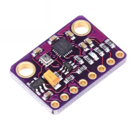
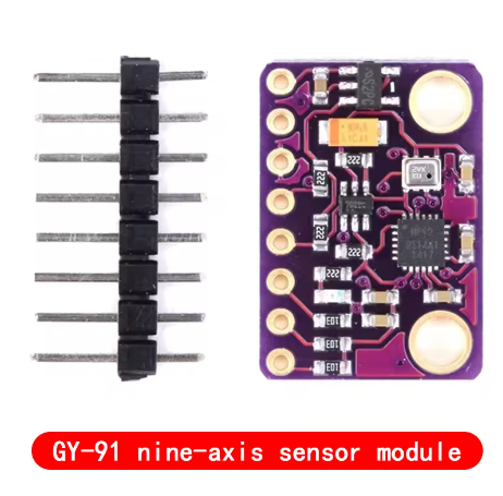
Product Overview
The GY-91 10DOF IMU Sensor Module is a compact motion tracking board that combines the MPU9250 9-axis motion sensor with the BMP280 high-precision barometric pressure sensor. This module integrates a 3-axis gyroscope, 3-axis accelerometer, and a barometer, making it ideal for applications requiring motion tracking, orientation sensing, and altitude measurement .
Please Note: This is a refurbished chip version. The magnetometer (compass) function is NOT operational on this module .
The MPU9250 is a second-generation 9-axis Motion Tracking device that features a 16-bit ADC for high-resolution data output and supports both I2C and SPI communication protocols. The BMP280 provides accurate pressure and temperature readings, enabling altitude calculation .
The module operates from 3V to 5V power supply thanks to an onboard low-dropout regulator, making it directly compatible with both 3.3V and 5V systems such as Arduino, ESP32, ESP8266, and Raspberry Pi .
Functional Sensors
Key Features
-
10-DOF Sensing: Combines 6-axis motion sensing (gyro + accel) with barometric pressure for altitude
-
MPU9250 Motion Sensor: 3-axis gyroscope + 3-axis accelerometer with 16-bit ADC output
-
BMP280 Barometer: High-precision pressure and temperature sensor for altitude measurement
-
Dual Communication Protocols: Supports both I2C and SPI for flexible microcontroller integration
-
Selectable Measurement Ranges:
-
Gyroscope: ±250, ±500, ±1000, ±2000°/s
-
Accelerometer: ±2g, ±4g, ±8g, ±16g
-
Pressure Range: 300 – 1100 hPa
-
Wide Operating Voltage: 3V – 5V DC (onboard low-dropout regulator)
-
16-bit Data Output: High-resolution conversion for motion data
-
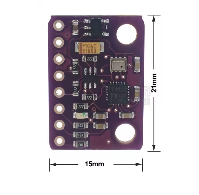
Compact Size: Small footprint measuring approximately 14.3mm × 20.5mm
-
Standard Pin Spacing: 2.54mm pitch for easy breadboard integration
-
Operating Temperature: -40°C to +85°C
Technical Specifications
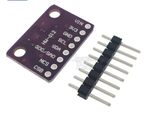
Pinout & Connection Guide
Pin Definitions
I2C Mode Wiring (Recommended)
For I2C communication (simplest wiring):
I2C Addresses
Usage Guide
Important Notes Before Use
-
Magnetometer Non-Functional: This refurbished unit has a non-operational magnetometer. You will only have access to 6-axis motion data (gyroscope + accelerometer) and barometer data. The I2C address 0x0C (AK8963 magnetometer) will not respond .
-
Gyroscope & Accelerometer: These sensors are fully functional and can be used for orientation tracking (pitch and roll). Yaw (heading) will drift over time without magnetometer correction.
-
SDO/SAO Connection: For stable I2C communication and proper address configuration, connect the SAO pin to GND or VCC. Leaving it floating may cause erratic behavior or failure to detect the MPU9250 .
Software Setup (Arduino IDE)
Step 1: Install Required Libraries
Install the following libraries via Arduino Library Manager:
Step 2: Basic Test Sketch (Gyroscope + Accelerometer + Barometer)
GY-91 Refurbished – Gyroscope, Accelerometer, and Barometer Read Example
Note: Magnetometer is not functional on this module
*/
#include <Wire.h>
#include <MPU9250.h>
#include <Adafruit_BMP280.h>
MPU9250 mpu;
Adafruit_BMP280 bmp;
void setup() {
Serial.begin(115200);
Wire.begin();
if (!mpu.setup(0x68)) {
Serial.println("MPU9250 sensor not found! Check wiring.");
while (1);
}
mpu.setGyroRange(2000);
mpu.setAccelRange(16);
if (!bmp.begin(0x76)) {
Serial.println("BMP280 not found!");
while (1);
}
Serial.println("GY-91 Ready (Magnetometer Not Functional)");
Serial.println("------------------------------------------");
}
void loop() {
if (mpu.update()) {
float ax = mpu.getAccX();
float ay = mpu.getAccY();
float az = mpu.getAccZ();
float gx = mpu.getGyroX();
float gy = mpu.getGyroY();
float gz = mpu.getGyroZ();
float temperature = bmp.readTemperature();
float pressure = bmp.readPressure();
float altitude = bmp.readAltitude(1013.25);
float pitch = atan2(-ax, sqrt(ay * ay + az * az)) * 180 / PI;
float roll = atan2(ay, az) * 180 / PI;
Serial.print("Accel (g): ");
Serial.print(ax); Serial.print(", ");
Serial.print(ay); Serial.print(", ");
Serial.println(az);
Serial.print("Gyro (°/s): ");
Serial.print(gx); Serial.print(", ");
Serial.print(gy); Serial.print(", ");
Serial.println(gz);
Serial.print("Pitch: ");
Serial.print(pitch);
Serial.print("°, Roll: ");
Serial.println(roll);
Serial.print("Temperature: ");
Serial.print(temperature);
Serial.println(" °C");
Serial.print("Pressure: ");
Serial.print(pressure);
Serial.println(" Pa");
Serial.print("Altitude: ");
Serial.print(altitude);
Serial.println(" m");
Serial.println("------------------------------------------");
}
delay(100);
}
Step 3: Verifying I2C Addresses
Run this I2C scanner to verify which sensors are detected:
#include <Wire.h>

void setup() {
  Wire.begin();
  Serial.begin(9600);
  Serial.println("I2C Scanner");
}

void loop() {
  byte error, address;
  int nDevices = 0;

  for(address = 1; address < 127; address++) {
    Wire.beginTransmission(address);
    error = Wire.endTransmission();

    if(error == 0) {
      Serial.print("I2C device found at address 0x");
      if(address < 16) Serial.print("0");
      Serial.println(address, HEX);
      nDevices++;
    }
  }

  if(nDevices == 0) Serial.println("No I2C devices found");
  delay(5000);
}
Expected Output: You should see addresses 0x68 (MPU9250 gyro/accel) and 0x76 or 0x77 (BMP280). Address 0x0C (magnetometer) will NOT appear.
Q: Why is the magnetometer not functional on this module?
This is a refurbished unit where the magnetometer component is not operational. Only the gyroscope, accelerometer, and BMP280 barometer work. This is a known characteristic of some refurbished GY-91 modules .
Q: Can I still use this module for orientation tracking?
Yes, but with limitations. You can track pitch and roll (tilt) accurately using the accelerometer. However, yaw (heading or compass direction) will drift over time without a functional magnetometer. For applications requiring absolute heading, consider adding a separate magnetometer module or using a fully functional IMU .
Q: What are the I2C addresses of the working sensors?
The MPU9250 (gyroscope + accelerometer) responds at address 0x68 (default). The BMP280 responds at address 0x76 or 0x77. The magnetometer address 0x0C will not respond.
Q: Why does my I2C scan only show two addresses instead of three?
This is expected. A fully functional GY-91 would show three addresses: MPU9250 (0x68), AK8963 magnetometer (0x0C), and BMP280 (0x76/0x77). The missing address 0x0C confirms the magnetometer is non-functional .
Q: Can I use this module with a 5V Arduino Uno?
Yes. The module includes an onboard voltage regulator that accepts 3V–5V input. Connect VIN to 5V and SDA/SCL directly to the I2C pins .
Q: Can I use this module with ESP32 or ESP8266?
Yes. Connect VIN to 3.3V and SDA/SCL to the appropriate I2C pins (GPIO21/22 for ESP32, GPIO4/5 for ESP8266). The same libraries work on these platforms.
Q: Why is the magnetometer on many GY-91 modules non-functional?
Refurbished and clone MPU9250 chips often have a defective AK8963 magnetometer IC. On the original MPU-9250, the magnetometer is a separate IC within the same package. If that IC is defective or missing, the gyroscope and accelerometer may still function normally .
Q: How do I correctly wire the SAO/AD0 pin?
Connect the SAO pin to GND (for address 0x68) or VCC (for address 0x69) using a pull-up or pull-down resistor. Leaving it floating may cause the MPU9250 to not respond properly .
Q: Does the BMP280 work on this module?
Yes. The BMP280 barometric pressure and temperature sensor is fully functional and can be used for altitude measurement and weather monitoring .
Q: What are typical applications for this module?
Despite the missing magnetometer, this module is useful for:
-
Drone flight stabilization (gyro + accel are sufficient for rate control)
-
Self-balancing robots (tilt detection)
-
Altitude measurement (barometer)
-
Orientation tracking where absolute heading is not required