Product Overview
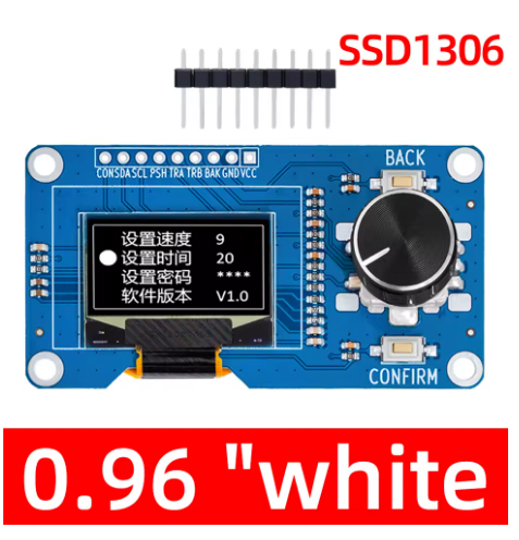
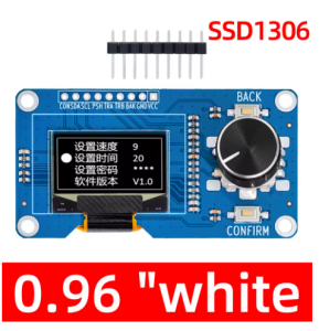
The 0.96-inch OLED Display Module with EC11 Rotary Encoder is an all-in-one human-machine interface (HMI) solution that combines a high-contrast 128×64 pixel OLED screen with an incremental rotary encoder featuring a push-button switch . This integrated module is specifically designed for projects requiring both visual feedback and precise user input, making it ideal for menu navigation, parameter adjustment, and interactive control systems.
The module features a 0.96-inch monochrome OLED display driven by the reliable SSD1306 controller, communicating via the simple I2C interface using only two data lines (SDA and SCL) . The EC11 incremental rotary encoder provides smooth rotational input with detents for tactile feedback, plus a push-button function for selection or confirmation actions .
OLED (Organic Light Emitting Diode) technology requires no backlight, as each pixel emits its own light. This self-emissive design provides true blacks (inactive pixels are completely off), excellent contrast, and wide viewing angles—ensuring the display remains readable in various lighting conditions while consuming minimal power.
Whether you are building a smart thermostat, a CNC controller pendant, a digital audio interface, or an IoT configuration panel, this integrated display and encoder module provides a compact, professional solution that simplifies wiring and reduces component count .
Key Features
-
Integrated Display + Encoder: Combines a 0.96″ 128×64 OLED display with an EC11 rotary encoder (with push-button) on a single PCB – a complete HMI solution
-
I2C Communication: The OLED display uses I2C protocol, requiring only 2 pins (SDA/SCL) for communication – saves valuable GPIO resources
-
EC11 Incremental Encoder: Features 20 pulses per revolution with detents for tactile feedback, plus a built-in push-button switch for selection/confirmation
-
SSD1306 Driver IC: Industry-standard controller with built-in display buffer and extensive library support (U8g2, Adafruit_SSD1306)
-
High-Contrast OLED Display: 128×64 pixel resolution with true black background and bright monochrome pixels (white, blue, or yellow options)
-
Wide Voltage Compatibility: Operates on 3.3V – 5V logic, compatible with Arduino, ESP32, ESP8266, STM32, and Raspberry Pi
-
Compact All-in-One Design: Small PCB footprint (approximately 65×35mm) reduces wiring complexity and component clutter
-
Wide Operating Temperature: Rated for -20°C to +70°C, suitable for various environments
Technical Specifications
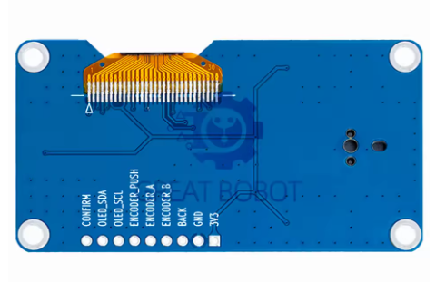
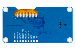
Pinout & Connection Guide
The module typically features a 9-pin interface . Pin labeling may vary slightly between manufacturers; always verify the silkscreen on your specific board.
Pin Definitions
Important: The I2C address for the OLED display is typically 0x3C (or 0x3D on some variants). Run an I2C scanner sketch to verify if you have trouble detecting the device .
Wiring Diagram (Arduino Uno)
Usage Guide
Software Setup (Arduino IDE)
Step 1: Install Required Libraries
Install the following libraries via Arduino Library Manager (Sketch → Include Library → Manage Libraries):
-
“U8g2” by Oliver Kraus – Display library (recommended, supports many fonts)
-
“Adafruit GFX” + “Adafruit SSD1306” – Alternative display libraries
-
“Rotary” by Ben Buxton – Encoder reading library
-
“Button2” – Button debouncing library
Step 2: Basic Test Sketch
#include <Arduino.h>
#include <U8g2lib.h>
#include <Wire.h>
#include <Rotary.h>
U8G2_SSD1306_128X64_NONAME_F_HW_I2C u8g2(U8G2_R0, U8X8_PIN_NONE);
#define ENC_A 2
#define ENC_B 4
#define ENC_SW 3
Rotary rotary = Rotary(ENC_A, ENC_B);
volatile int encoderPos = 0;
bool buttonPressed = false;
void setup() {
u8g2.begin();
u8g2.enableUTF8Print();
u8g2.setFont(u8g2_font_ncenB08_tr);
pinMode(ENC_A, INPUT_PULLUP);
pinMode(ENC_B, INPUT_PULLUP);
pinMode(ENC_SW, INPUT_PULLUP);
attachInterrupt(digitalPinToInterrupt(ENC_A), encoderISR, CHANGE);
attachInterrupt(digitalPinToInterrupt(ENC_B), encoderISR, CHANGE);
attachInterrupt(digitalPinToInterrupt(ENC_SW), buttonISR, FALLING);
Serial.begin(115200);
}
void loop() {
u8g2.firstPage();
do {
u8g2.drawStr(0, 15, "EC11 Encoder Demo");
u8g2.drawStr(0, 35, "Position: ");
u8g2.setCursor(70, 35);
u8g2.print(encoderPos);
if (buttonPressed) {
u8g2.drawStr(0, 55, "Button Pressed!");
buttonPressed = false;
}
} while ( u8g2.nextPage() );
delay(50);
}
void encoderISR() {
unsigned char result = rotary.process();
if (result == DIR_CW) encoderPos++;
else if (result == DIR_CCW) encoderPos--;
}
void buttonISR() {
buttonPressed = true;
}
Step 3: Encoder Debouncing
Mechanical encoders like the EC11 require debouncing. If you experience erratic readings, implement a simple debounce filter in software:
#define DEBOUNCE_DELAY 5
unsigned long lastDebounceTime = 0;
void encoderISR() {
unsigned long now = millis();
if (now - lastDebounceTime > DEBOUNCE_DELAY) {
unsigned char result = rotary.process();
if (result == DIR_CW) encoderPos++;
else if (result == DIR_CCW) encoderPos--;
lastDebounceTime = now;
}
}
Raspberry Pi Setup (Python)
-
Enable I2C: sudo raspi-config → Interface Options → I2C → Yes
-
Install required libraries:
sudo apt-get install python3-pip
pip3 install luma.oled RPi.GPIO
-
Python example code:
from luma.core.interface.serial import i2c
from luma.oled.device import ssd1306
from luma.core.render import canvas
import RPi.GPIO as GPIO
import time
ENC_A = 17
ENC_B = 18
ENC_SW = 27
GPIO.setmode(GPIO.BCM)
GPIO.setup(ENC_A, GPIO.IN, pull_up_down=GPIO.PUD_UP)
GPIO.setup(ENC_B, GPIO.IN, pull_up_down=GPIO.PUD_UP)
GPIO.setup(ENC_SW, GPIO.IN, pull_up_down=GPIO.PUD_UP)
serial = i2c(port=1, address=0x3C)
device = ssd1306(serial, width=128, height=64)
counter = 0
def encoder_callback(channel):
global counter
if GPIO.input(ENC_A) == GPIO.input(ENC_B):
counter += 1
else:
counter -= 1
GPIO.add_event_detect(ENC_A, GPIO.BOTH, callback=encoder_callback)
GPIO.add_event_detect(ENC_B, GPIO.BOTH, callback=encoder_callback)
with canvas(device) as draw:
draw.rectangle(device.bounding_box, outline="white", fill="black")
draw.text((10, 20), "EC11 Encoder Demo", fill="white")
draw.text((10, 40), f"Position: {counter}", fill="white")
EC11 Encoder Pinouts
The EC11 encoder features three primary terminals for rotation detection plus two for the push button :
The encoder produces 20 pulses per full rotation with detents providing tactile feedback at each step . The push button is a standard momentary switch requiring a pull-up resistor (internal pull-up can be used).
Q: What is the I2C address of the OLED display?
The default I2C address is typically 0x3C. Some modules may use 0x3D depending on the SA0 pin configuration . Run an I2C scanner sketch to verify the address if you have trouble detecting the device.
Q: Can I use this display and encoder with a 5V Arduino Uno?
Yes. The module operates on 3.3V – 5V, so it is compatible with both 5V (Arduino) and 3.3V (ESP32) logic systems . Connect VCC to 5V and the I2C pins (SCL/SDA) directly to A5/A4.
Q: How many pins does this module require to operate?
The module typically requires 4 pins for the display (VCC, GND, SCL, SDA) plus 3 pins for the encoder (A, B, C) and one for the push button (SW), totaling 8 pins. However, the encoder common (C) can share GND with the display, reducing the count .
Q: Does the EC11 encoder require external pull-up resistors?
Yes, the EC11 encoder channels (A and B) and the push button (SW) require pull-up resistors. Most microcontrollers have internal pull-ups that can be enabled (INPUT_PULLUP). If you experience unstable readings, add external 10kΩ resistors to VCC .
Q: Why is my encoder reading erratic or missing steps?
Mechanical encoders like the EC11 suffer from contact bounce. Implement software debouncing (typically 5-10ms delay in the interrupt handler) or use a library like Rotary that handles debouncing . Also, ensure you are using interrupt-capable pins for the encoder channels.
Q: What libraries work best with the SSD1306 display?
The U8g2 library is highly recommended for its extensive font support and reliability . Alternatives include Adafruit_SSD1306 (paired with Adafruit_GFX) for simpler graphics, and the LCD5110 library for basic text operations. All are available through the Arduino Library Manager.
Q: Can I use this module with ESP32 or ESP8266?
Yes. Both ESP32 and ESP8266 use 3.3V logic, which is directly compatible with this module. Connect VCC to 3.3V, GND to GND, and the I2C pins to the default I2C pins (GPIO21/GPIO22 for ESP32, GPIO4/GPIO5 for ESP8266). The same libraries work on these platforms.
Q: What are typical applications for this OLED + encoder module?
This module is ideal for:
-
Menu navigation in embedded systems (selecting options, adjusting parameters)
-
CNC / 3D printer control pendants – manual axis jogging
-
Audio equipment – volume control and menu selection
-
IoT device configuration panels – setting Wi-Fi credentials, thresholds
-
Test and measurement instruments – frequency/amplitude adjustment
Q: What is the difference between EC11 and other rotary encoders (PEC11)?
EC11 and PEC11 are functionally very similar—both are incremental encoders with detents and push-button switches . The EC11 produces 20 pulses per revolution, while some PEC11 variants produce 24 detents. Most hobbyist encoders are interchangeable as long as the pinout and voltage ratings match .
Q: How do I read both encoder rotation and button press simultaneously?
Use interrupts for the encoder channels to capture rotation events without missing steps . The button can be read in the main loop with debouncing, or also via interrupt. The example code above demonstrates using attachInterrupt() for both encoder channels and the button .
Q: What is the lifespan of the EC11 encoder?
EC11 encoders are rated for approximately 30,000 to 50,000 rotation cycles and 10,000 to 30,000 push-button presses depending on the manufacturer. For applications requiring higher durability, consider industrial-grade encoders.
Q: Can I power this module from a battery for portable projects?
Yes. OLED displays are power-efficient because only lit pixels consume power. The module typically draws 10-25mA depending on displayed content. For maximum battery life, implement sleep modes to turn off the display when not actively in use (send command 0xAE to the SSD1306).