Product Overview
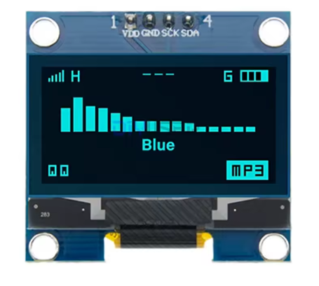
The 1.3-inch I2C OLED Display Module is a compact, high-contrast monochrome screen designed for embedded projects requiring crisp visual output without consuming excessive power or I/O pins. Powered by the SH1106 driver IC and featuring a sharp 128×64 pixel resolution, this display delivers vibrant blue text, detailed graphics, and custom icons on a true black background .
Unlike traditional LCDs that require a power-hungry backlight, OLED (Organic Light Emitting Diode) technology allows each pixel to emit its own light. This self-emissive design provides true blacks (inactive pixels are completely off), an exceptional contrast ratio, and >160° viewing angles – ensuring the display remains readable from almost any angle .
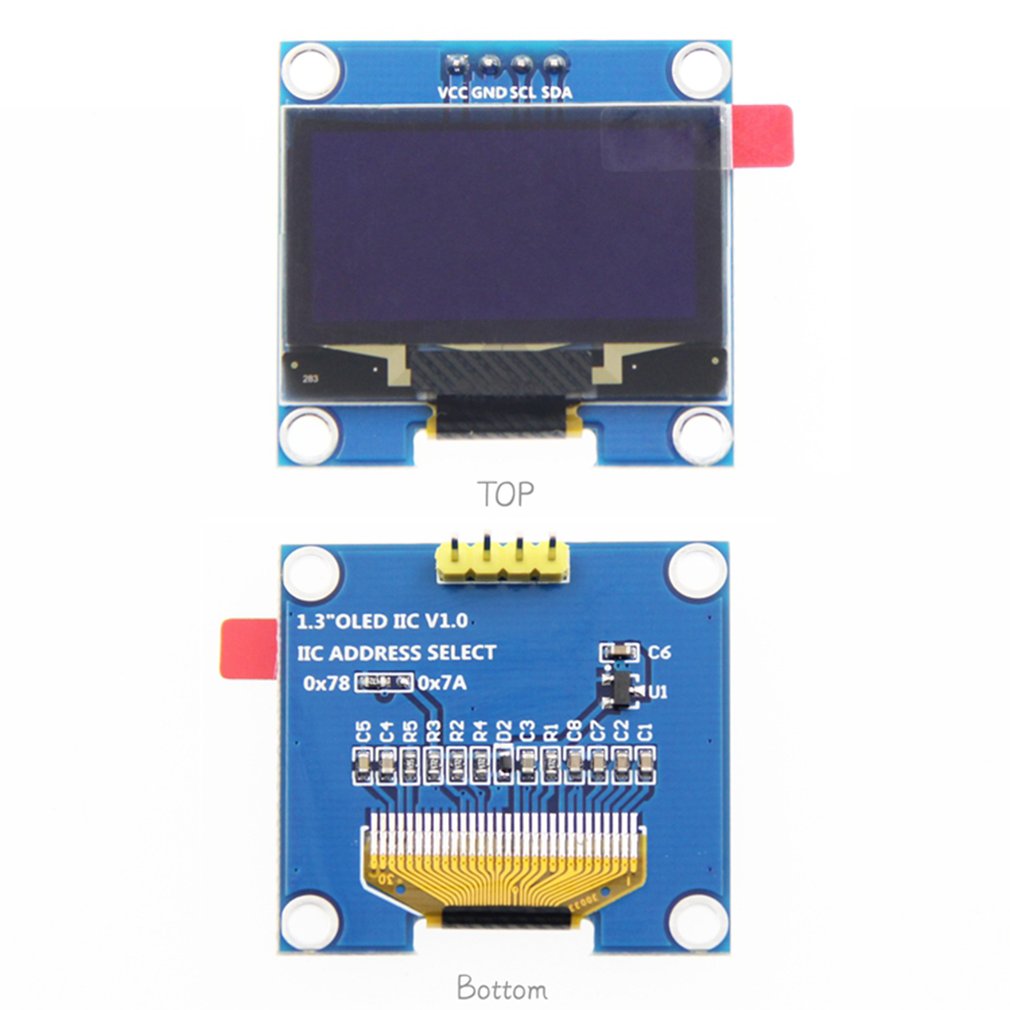
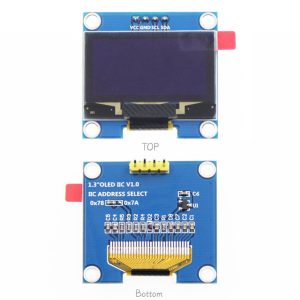
The module uses the ultra-simple 4-pin I2C interface (VCC, GND, SCL, SDA), requiring only two data lines to connect to your microcontroller. This preserves valuable I/O pins for other sensors and peripherals. With support for both 3.3V and 5V logic, it is directly compatible with Arduino, ESP32, ESP8266, Raspberry Pi, STM32, and most other development boards – no level shifters required .
Key Features
-
Larger 1.3-Inch Active Area: 34.5mm × 19mm display area offers better readability than 0.96″ screens while maintaining 128×64 resolution
-
128×64 Pixel Resolution: High-definition display capable of showing detailed graphics, bitmaps, and up to 8 lines of text
-
SH1106 Driver IC: Industry-standard controller designed for 132×64-bit SRAM (supports 128×64 active area)
-
I2C Interface: 4-pin connection (VCC, GND, SCL, SDA) requires only 2 data lines – saves valuable I/O pins
-
Wide Voltage Compatibility: Operates on 3.3V–5V DC, compatible with both 5V (Arduino) and 3.3V (ESP32/ESP8266) logic
-
Ultra-Low Power Consumption: No backlight means lower battery drain – ideal for portable and battery-powered projects
-
Wide Viewing Angle: >160° visibility ensures clear readouts from almost any angle without contrast shift
-
Wide Operating Temperature: Industrial-grade rating of -40°C to +85°C, suitable for various environments
Technical Specifications
SH1106 vs SSD1306: Important Note
Unlike 0.96″ displays that typically use the SSD1306 driver, this 1.3″ OLED uses the SH1106 driver. The SH1106 has internal RAM of 132×64 pixels (display area is 128×64) – the extra 4 columns are not visible. This difference means that while many SSD1306 libraries will work with SH1106 , for best results use libraries that explicitly support SH1106, such as:
-
Adafruit SH1106 – with GFX library support
-
U8g2 library – supports both SH1106 and SSD1306 with many fonts
-
MycilaEasyDisplay – supports SH1106 for ESP32
Pinout & Connection Guide
The 4-pin I2C interface is extremely simple, making it perfect for beginners and rapid prototyping.
I2C Pin Mapping for Common Development Boards
Wiring Diagram (Arduino Uno)
OLED Module          →    Arduino Uno
─────────────────────────────────────
VCC                  →    5V (or 3.3V)
GND                  →    GND
SCL                  →    A5
SDA                  →    A4
Note: The display’s logic pins are designed for 3.3V signals. When used with 5V Arduino, the 5V power is acceptable, but the I2C signals should ideally be level-shifted for long-term reliability .
Usage Guide
Software Setup (Arduino IDE)
Step 1: Install Required Libraries
You need graphics and driver libraries for SH1106. Two popular options:
Option A: Adafruit SH1106 (Recommended for SH1106)
-
Open Arduino IDE → Sketch → Include Library → Manage Libraries
-
Search for and install:
Option B: U8g2 (Multi-driver support with many fonts)
Step 2: I2C Address Verification
Most 1.3″ I2C OLED modules use address 0x3C . You can verify by running this scanner:
#include <Wire.h>

void setup() {
  Wire.begin();
  Serial.begin(9600);
  Serial.println("I2C Scanner");
}

void loop() {
  byte error, address;
  int nDevices = 0;

  for(address = 1; address < 127; address++) {
    Wire.beginTransmission(address);
    error = Wire.endTransmission();

    if(error == 0) {
      Serial.print("I2C device found at address 0x");
      if(address < 16) Serial.print("0");
      Serial.println(address, HEX);
      nDevices++;
    }
  }

  if(nDevices == 0) Serial.println("No I2C devices found");
  delay(5000);
}
Step 3: Basic Test Sketch (Adafruit SH1106)
#include <Wire.h>
#include <Adafruit_GFX.h>
#include <Adafruit_SH1106.h>
#define SCREEN_WIDTH 128
#define SCREEN_HEIGHT 64
#define OLED_RESET 4
Adafruit_SH1106 display(OLED_RESET);
void setup() {
Serial.begin(9600);
if(!display.begin(SH1106_SWITCHCAPVCC, 0x3C)) {
Serial.println(F("SH1106 allocation failed"));
for(;;);
}
display.clearDisplay();
display.setTextSize(2);
display.setTextColor(WHITE);
display.setCursor(10, 25);
display.println("1.3 OLED");
display.println("Ready!");
display.display();
}
void loop() {
}
Step 4: Alternative using U8g2 Library
#include <Arduino.h>
#include <U8g2lib.h>
#include <Wire.h>

U8G2_SH1106_128X64_NONAME_F_HW_I2C u8g2(U8G2_R0, U8X8_PIN_NONE);

void setup() {
  u8g2.begin();
}

void loop() {
  u8g2.firstPage();
  do {
    u8g2.setFont(u8g2_font_ncenB08_tr);
    u8g2.drawStr(0, 20, "1.3 OLED");
    u8g2.drawStr(0, 40, "128x64");
    u8g2.drawStr(0, 60, "SH1106");
  } while ( u8g2.nextPage() );
  delay(1000);
}
Understanding the Display Buffer Workflow
Most OLED libraries use a buffer-based drawing system:
-
Drawing functions (e.g., drawPixel, println, fillRect) write to an in-memory buffer, not directly to the screen
-
The screen does NOT update immediately
-
You must call display.display() (Adafruit) or use the nextPage() loop (U8g2) to transfer buffer contents to the OLED panel
This double-buffering technique prevents screen flicker and allows you to build complex frames efficiently.
Q: What is the difference between the 1.3" I2C OLED and 0.96" OLED displays?
The 1.3″ version has a larger active area (29.42mm × 14.7mm vs 21.74mm × 10.86mm) while maintaining the same 128×64 resolution, resulting in 110 DPI . Additionally, the 1.3″ typically uses the SH1106 driver, while 0.96″ often uses SSD1306.
Q: Can I use an SSD1306 library with this SH1106 display?
Generally yes – many users report that SSD1306 libraries work with SH1106 displays . However, the SH1106 has different internal RAM organization (132×64 vs 128×64). For guaranteed compatibility, use libraries that explicitly support SH1106, such as Adafruit_SH1106, U8g2, or MycilaEasyDisplay .
Q: What is the default I2C address for this display?
The default I2C address is 0x3C (7-bit address). When configured for I2C mode, the DC pin (when present) determines the address – connected to GND gives 0x3C; to VCC gives 0x3D .
Q: How does OLED technology compare to LCD?
OLEDs are self-emissive (no backlight needed), providing true blacks, higher contrast ratio, wider viewing angles (>160°), and lower power consumption. Traditional LCDs require a backlight that constantly draws power and cannot achieve true black.
Q: What is the lifespan of the OLED display?
Rated lifespan is approximately 20,000-30,000 hours of continuous operation (about 2.5-3.5 years). Avoid displaying static images for extremely long periods to prevent uneven pixel wear (“burn-in”).
Q: How much current does the OLED display draw?
Power consumption depends on how many pixels are lit:
-
Typical text/dashboard (~25% pixels lit): ~20mA
-
All pixels ON (full screen white): ~40mA
-
Display off (standby): minimal
Q: Can I adjust the display brightness?
Yes. The SH1106 supports contrast adjustment through library commands. In Adafruit library, use display.setContrast(value) where value ranges from 0 to 255.
Q: Is this display readable in direct sunlight?
OLEDs have excellent contrast, making them readable in most lighting conditions. However, like all emissive displays, direct bright sunlight may reduce perceived contrast compared to reflective LCDs.
Q: Can I use this display with 3.3V logic microcontrollers?
Yes, the display is designed to work with 3.3V logic. For ESP32, ESP8266, and Raspberry Pi, connect VCC to 3.3V and SDA/SCL directly to GPIO pins.
Q: Does this module have pull-up resistors for I2C?
Most modules include onboard pull-up resistors. If your specific module doesn’t have them, you may need to add external 4.7kΩ-10kΩ pull-up resistors on SDA and SCL lines to VCC.
Q: What should I do if my display stays blank after power-up?
Check these common issues:
-
Wiring – verify VCC→5V (or 3.3V), GND→GND, SCL→A5, SDA→A4
-
Confirm I2C address using scanner sketch (should be 0x3C)
-
Ensure display initialization is called before drawing
-
Call display.display() after drawing operations
-
Try adjusting contrast setting in code
Q: Can I use this display with Raspberry Pi?
Yes. Enable I2C via raspi-config, then connect VCC to 3.3V (Pin 1), GND to GND, SCL to GPIO3 (Pin 5), and SDA to GPIO2 (Pin 3). Use Python libraries like luma.oled or Adafruit_CircuitPython_SSD1306.
Q: What can I build with this 1.3" OLED display?
Popular applications include:
-
IoT sensor stations: Display temperature, humidity, and pressure readings
-
Smart home control panels: System status and device controls
-
Data loggers: Real-time sensor data visualization
-
Diagnostic tools: Battery testers and instrument displays
-
Menu interfaces: Handheld device navigation
-
Wearable devices: Compact displays for wearables
-
Retro gaming: Small game displays
Q: What libraries are recommended for beginners?
For beginners, the Adafruit SH1106 library (with Adafruit GFX) is well-documented and easiest to get started. U8g2 offers more font options but has a slightly steeper learning curve. Both are available through the Arduino Library Manager.
Q: Can I display custom bitmap images on this display?
Yes. Use tools like LCD Image Converter, Image2CPP, or online converters to transform 128×64 monochrome bitmap images into C arrays. In Adafruit library, use display.drawBitmap(x, y, array, width, height, color) to display images.