Product Overview
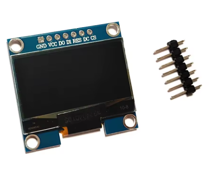
The 1.3-inch White 7-Pin OLED Display Module is a compact, high-contrast monochrome graphic display designed for embedded applications requiring crisp visual output and flexible connectivity. Powered by the SH1106 driver IC with a sharp 128×64 pixel resolution, this 7-pin variant offers the highest flexibility, supporting both 4-wire SPI (default) and I2C communication protocols .
The dedicated Chip Select (CS) pin allows multiple SPI devices to share the same bus without conflicts—essential for complex projects with multiple peripherals such as SD cards, sensors, or additional displays .
OLED (Organic Light Emitting Diode) technology requires no backlight, as each pixel emits its own light. This self-emissive design delivers true blacks (inactive pixels are completely off), exceptional contrast, and >160° viewing angles . The bright white monochrome display ensures excellent readability in all lighting conditions while consuming minimal power—approximately 0.04W during normal operation (20mA typical) .
The module includes an on-board voltage regulator that accepts 3.3V–5.5V power, making it compatible with both 5V (Arduino) and 3.3V (ESP32, Raspberry Pi) systems . Four mounting holes (for M3 or #4 screws) provide secure installation options .
Key Features & Specifications
Pinout & Connection Guide
The 7-pin SPI interface uses standard pin functions for easy connectivity :
Wiring to 3.3V Microcontrollers (ESP32, Raspberry Pi)
Logic voltage matches – direct connection, no level shifters needed.
Wiring to 5V Microcontrollers (Arduino Uno)
⚠️ CRITICAL: The logic pins (D0, D1, RES, DC, CS) are NOT 5V tolerant. You must use 3.3V logic level shifters on all these pins . The VCC power pin IS 5V tolerant and can connect directly to 5V.
Alternative: Use a 3.3V board (ESP32, Arduino Pro Mini 3.3V, Raspberry Pi) to avoid level shifters entirely.
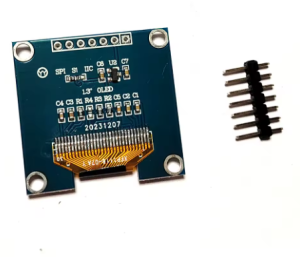
SPI vs I2C Mode
The 7-pin module supports both SPI and I2C protocols. The default configuration is 4-wire SPI, but can be switched to I2C by modifying resistors on the back of the PCB .
Usage Guide
Software Setup (Arduino IDE)
Step 1: Install the U8g2 Library
The U8g2 library by Oliver Kraus is the most reliable choice for SH1106 displays .
-
Open Arduino IDE → Sketch → Include Library → Manage Libraries
-
Search for “U8g2” by Oliver Kraus
-
Click Install
Step 2: Basic Test Sketch (Hardware SPI Mode)
#include <Arduino.h>
#include <U8g2lib.h>
#include <SPI.h>
U8G2_SH1106_128X64_NONAME_1_4W_HW_SPI u8g2(U8G2_R0, 5, 2, 4);
void setup() {
u8g2.begin();
u8g2.enableUTF8Print();
u8g2.setFont(u8g2_font_ncenB08_tr);
u8g2.setDrawColor(1);
}
void loop() {
u8g2.firstPage();
do {
u8g2.drawStr(0, 15, "1.3 OLED");
u8g2.drawStr(0, 35, "128x64");
u8g2.drawStr(0, 55, "SPI 7-Pin");
u8g2.drawStr(0, 75, "White SH1106");
} while ( u8g2.nextPage() );
delay(1000);
}
Step 3: Software SPI Mode (Any Pins)
If you prefer not to use hardware SPI pins:
#include <Arduino.h>
#include <U8g2lib.h>
U8G2_SH1106_128X64_NONAME_1_4W_SW_SPI u8g2(U8G2_R0, 13, 11, 10, 9, 8);
void setup() {
u8g2.begin();
u8g2.setFont(u8g2_font_ncenB08_tr);
}
void loop() {
u8g2.firstPage();
do {
u8g2.drawStr(0, 20, "SH1106 Ready!");
} while ( u8g2.nextPage() );
delay(1000);
}
Raspberry Pi Setup (Python)
-
Enable SPI: sudo raspi-config → Interface Options → SPI → Yes
-
Install required libraries:
sudo apt-get install python3-pip
pip3 install luma.oled
-
Python example code:
from luma.core.interface.serial import spi
from luma.oled.device import sh1106
from luma.core.render import canvas
serial = spi(port=0, device=0, gpio_DC=24, gpio_RST=25, gpio_CS=8)
device = sh1106(serial)
with canvas(device) as draw:
draw.rectangle(device.bounding_box, outline="white", fill="black")
draw.text((30, 20), "1.3 OLED", fill="white")
draw.text((30, 40), "SPI 128x64", fill="white")
SH1106 vs SSD1306 Important Note
The SH1106 driver has internal RAM of 132×64 pixels, while the visible area is 128×64 pixels. The column start address for SH1106 is 0x02, unlike SSD1306 which uses 0x00 . Most modern libraries (U8g2, Adafruit_SH110X) handle this automatically.
Power Management for Battery-Powered Projects
Only lit pixels consume power, making OLEDs excellent for battery-powered applications:
Q: What is the difference between the 7-pin version and the 4-pin I2C version?
The 7-pin version offers full SPI interface with a dedicated Chip Select (CS) pin. SPI is significantly faster than I2C (up to 10MHz vs 400kHz), making it ideal for animations, real-time data dashboards, and high refresh rate applications. The dedicated CS also allows multiple SPI devices to share the same bus .
Q: Can I use this display directly with a 5V Arduino Uno?
NO! The logic pins (D0, D1, RES, DC, CS) are NOT 5V tolerant . You must use 3.3V logic level shifters on all these pins. However, the VCC power pin IS 5V tolerant and can connect directly to 5V. For beginners, using a 3.3V board (ESP32, Raspberry Pi) is strongly recommended.
Q: Is this display compatible with ESP32 and Raspberry Pi?
Yes – both ESP32 and Raspberry Pi use 3.3V logic, which matches the display’s logic requirements. Connect directly without level shifters. Use 3.3V power for VCC as well .
Q: What is the difference between SH1106 and SSD1306 drivers?
The SH1106 driver has internal RAM of 132×64 pixels, while the visible area is 128×64 pixels. The SH1106 requires a column start address of 0x02, while SSD1306 uses 0x00 . Most modern libraries (U8g2, Adafruit) handle this automatically, but code written for SSD1306 may not work directly with SH1106 .
Q: Why does my display stay blank after power-up?
Common issues to check:
-
Logic voltage mismatch – if using 5V Arduino, did you use level shifters?
-
Wiring – verify VCC and GND connections
-
Library – ensure you selected the SH1106 driver in U8g2 (not SSD1306)
-
SPI pins – verify CLK and MOSI are connected to correct hardware SPI pins
-
CS pin – ensure CS is properly connected or held LOW
-
Reset sequence – power-on reset pulse may be needed
Q: Can I switch this display to I2C mode?
Yes. The module supports both SPI and I2C by configuring resistors on the back of the PCB . By default, it operates in 4-wire SPI mode. In I2C mode, the DC pin must be connected appropriately, and the I2C address is typically 0x3C (7-bit) .
Q: How do I use multiple SPI devices with this display?
The dedicated CS (Chip Select) pin allows multiple SPI devices on the same bus. Connect all devices’ CLK and MOSI pins together, but give each device a unique CS pin. Set the CS pin LOW only for the device you’re communicating with; set others HIGH .
Q: How many characters can the display show?
With the default 8×8 pixel font, approximately 16 characters × 8 lines = 128 characters total. With larger fonts (e.g., 16×16 pixels), about 8 characters × 4 lines = 32 characters. The 128×64 resolution provides excellent clarity for both text and graphics.
Q: What is the lifespan of the OLED display?
Rated lifespan is approximately 20,000-30,000 hours of continuous operation (about 2.5-3.5 years). Avoid displaying static images for extremely long periods to prevent uneven pixel wear (“burn-in”). For typical intermittent hobbyist use, this is not a concern.
Q: How do I display Chinese characters or custom fonts?
Chinese characters and custom fonts require a “font extraction” (taking modulus) tool to convert text into bitmap data arrays . Several tools are available online and through Arduino libraries. The U8g2 library also includes many fonts for different languages .