Product Overview
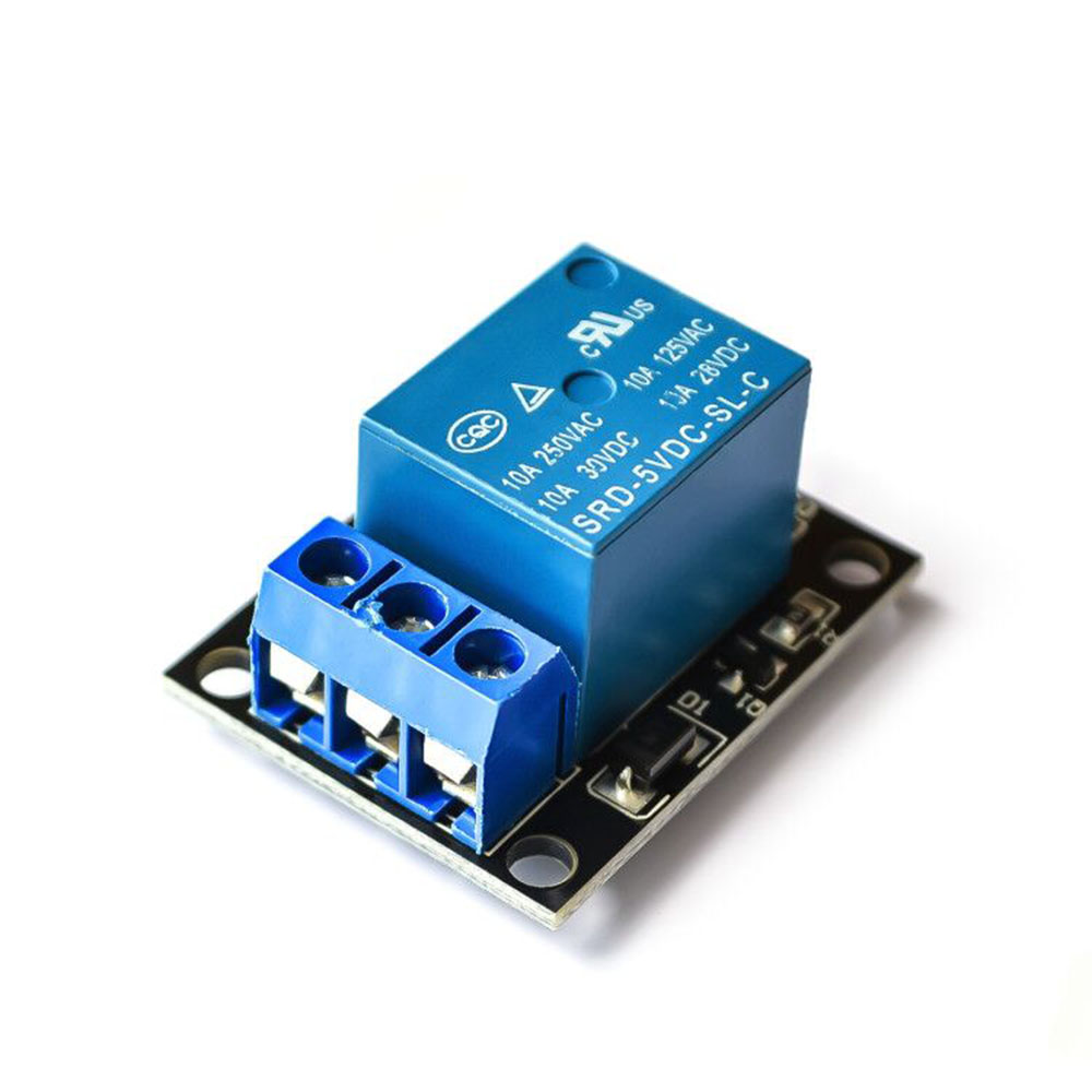
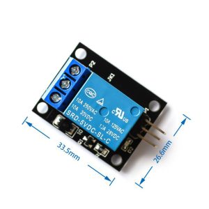
The 1 Channel Relay Module without Optocoupler is a simple, cost-effective solution for controlling high-power devices from low-voltage microcontrollers such as Arduino, ESP32, Raspberry Pi, PIC, AVR, and ARM . This module acts as an electrically operated switch that allows your low-voltage control signal (3.3V–5V) to safely switch high-voltage loads up to 250V AC or 30V DC at 10A .
Unlike optically isolated relay modules, this version uses a direct transistor drive circuit (typically an 8550 or 8050 transistor) to activate the relay coil . This design offers a lower cost and simpler circuit, making it ideal for hobbyist projects, educational use, and applications where isolation is not critical.
The module provides SPDT (Single Pole Double Throw) relay contacts, giving you access to both Normally Open (NO) and Normally Closed (NC) terminals. This allows you to configure your load to be either OFF by default (using NO) or ON by default (using NC) . Whether you’re controlling lights, fans, pumps, motors, or other household appliances, this relay module provides a reliable interface between your digital electronics and the physical world .
Key Features
-
Direct Transistor Drive: Uses 8550 or 8050 transistor to drive the relay coil, eliminating the need for optocoupler isolation
-
High Load Capacity: Relay contacts rated for 10A at 250V AC or 10A at 30V DC, suitable for controlling lights, fans, pumps, and small motors
-
Active Low Control: Input is active LOW—relay activates when the control pin is pulled LOW (0V) and deactivates when pulled HIGH (5V)
-
SPDT Contact Configuration: Provides Common (COM), Normally Open (NO), and Normally Closed (NC) terminals for flexible wiring options
-
Status Indicator LEDs: Includes a power LED (green) and a relay status LED (red) for visual confirmation of operation
-
Wide Operating Voltage: Accepts 3.75V to 6V DC power supply, with optimal operation at 5V
-
Low Quiescent Current: Consumes only 2mA when idle, and approximately 70mA when the relay is active
-
Standard Interface: 3-pin header (VCC, GND, IN) with 2.54mm pitch for easy connection to breadboards and microcontrollers
Technical Specifications
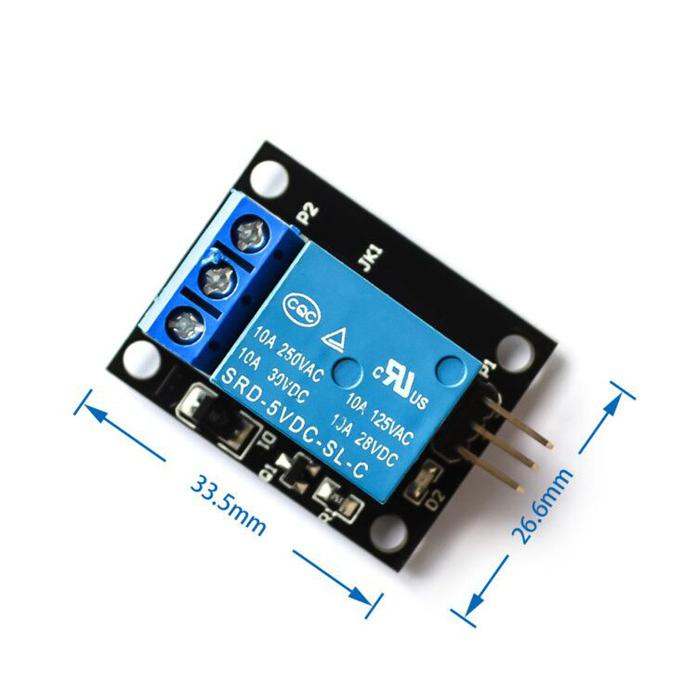
Pinout & Interface Guide
The module features clearly labeled pins and terminals for easy wiring:
Input Side (Control Interface)
Output Side (Load Interface)
Indicator LEDs
Usage Guide
Wiring Instructions
IMPORTANT: Always disconnect mains power before wiring high-voltage loads.
Basic Connection (Low-Voltage Control)
Load Connection
For a device that should be OFF by default (e.g., a lamp that turns on when relay activates):
-
Connect the positive/live wire of your power source to the COM terminal
-
Connect the positive/live wire of your load to the NO terminal
-
Connect the load’s neutral/ground wire directly to the power source
For a device that should be ON by default:
Example Arduino Code
The following code demonstrates basic relay control. The relay will turn on for 5 seconds and off for 5 seconds in a continuous loop .
const int relayPin = 7;
void setup() {
pinMode(relayPin, OUTPUT);
digitalWrite(relayPin, HIGH);
}
void loop() {
digitalWrite(relayPin, LOW);
delay(5000);
digitalWrite(relayPin, HIGH);
delay(5000);
}
Important Considerations
-
Power Supply: The module requires a stable 5V power supply capable of delivering at least 100mA (the relay draws ~70mA when active)
-
Control Signal: This module is active LOW—the relay activates when the IN pin is connected to GND (0V)
-
Load Limits: Do not exceed the relay’s rated voltage and current (250V AC / 30V DC, 10A). Exceeding these ratings may damage the module and create safety hazards
-
Inductive Loads: When controlling motors, pumps, or solenoids, add a flyback diode across the load to protect the relay contacts from voltage spikes
-
Isolation: This module does not provide optical isolation. The control circuit and the high-voltage load share a common ground path. Exercise caution when wiring
Q: What is the difference between this module and an optically isolated relay module?
This module uses a direct transistor (8550/8050) to drive the relay coil, while optically isolated modules use an optocoupler to separate the control circuit from the relay circuit. This version is more cost-effective but does not provide electrical isolation between your microcontroller and the high-voltage load
Q: What is the maximum load this relay can handle?
The relay contacts are rated for 10A at 250V AC or 10A at 30V DC . For inductive loads like motors, it is recommended to derate to 5A–8A to account for startup surges
Q: Can I use this relay with a 3.3V microcontroller like ESP32 or Raspberry Pi Pico?
Yes, but with caution. The module is designed for 5V control signals (active LOW). A 3.3V LOW signal is effectively 0V and will activate the relay. However, when driving the pin HIGH (3.3V), the module may not reliably deactivate if the threshold is too high. Using a level shifter or an NPN transistor is recommended for reliable operation
Q: What is the meaning of "active LOW"?
“Active LOW” means the relay activates when the IN pin is pulled LOW (connected to GND, 0V). When the IN pin is HIGH (connected to VCC, 5V), the relay is OFF. This is the opposite of “active HIGH” modules
Q: What is the difference between the NO and NC terminals?
-
NO (Normally Open): This terminal is disconnected from COM when the relay is OFF. When the relay activates, it connects to COM. Use NO for devices that should be OFF by default .
-
NC (Normally Closed): This terminal is connected to COM when the relay is OFF. When the relay activates, it disconnects. Use NC for devices that should be ON by default
Q: What power supply do I need for this module?
The module requires a 5V DC power supply capable of providing at least 100mA (the relay draws approximately 70mA when active). A common solution is to power it from the 5V pin of your Arduino, but ensure the total current draw does not exceed the Arduino’s capacity
Q: Why does the module have two LEDs?
The green LED (power indicator) lights up whenever the module is receiving power. The red LED (status indicator) lights up when the relay is activated (IN pin LOW), providing visual feedback of the relay state
Q: The relay clicks but my device doesn't turn on. What's wrong?
This indicates the relay is activating but the load circuit is not complete. Check:
-
The load’s neutral/ground is connected directly to the power source
-
The load’s live wire is correctly connected to NO or NC (depending on desired behavior)
-
The COM terminal is connected to the power source live wire
-
The load itself is functional
Q: The module gets warm during operation. Is this normal?
The relay coil draws approximately 70mA when active, which may cause slight warmth. If the module becomes hot, check that the load does not exceed the relay’s current rating and that the power supply voltage is stable
Q: How do I control this relay from a microcontroller?
Connect the module’s IN pin to a digital output pin on your microcontroller. Set the pin LOW to activate the relay (turn it ON), and set it HIGH to deactivate (turn it OFF). The example Arduino code above demonstrates this
Q: Can I control multiple relays with one microcontroller?
Yes. You can connect multiple relay modules to a single microcontroller, using a separate digital output pin for each module’s IN pin. Each relay can be controlled independently
Q: What is the lifespan of the relay?
The relay’s mechanical lifespan is typically 100,000 to 1,000,000 operations, depending on the load and operating conditions. For applications requiring extremely high switching frequencies, consider using a solid-state relay (SSR)
Q: How do I control AC appliances safely with this relay?
-
Always disconnect mains power before wiring
-
Connect the AC load between the COM and NO (or NC) terminals
-
Ensure the load’s voltage and current do not exceed the relay’s ratings
-
Use appropriately rated wire for the AC side
-
Consider adding a fuse for additional protection
Q: What can I build with this 1-channel relay module?
Popular applications include:
-
Home automation (lights, fans, appliances)
-
Water pump control for irrigation or aquariums
-
Motor speed and direction control (with appropriate drivers)
-
Security systems (alarms, locks)
-
Industrial equipment control
-
IoT smart home projects (with ESP32/ESP8266)
Q: Can I use this module to control a 220V water heater or high-power appliance?
Yes, as long as the appliance’s power consumption does not exceed the relay’s rating of 10A at 250V AC (approximately 2500W for resistive loads). For inductive loads like motors or compressors, derate to 5A–8A to account for startup current
Q: Can I use this relay with a Raspberry Pi?
Yes. Connect the relay’s IN pin to a GPIO pin on the Raspberry Pi. Use the RPi.GPIO library to control the pin (LOW to activate, HIGH to deactivate). Ensure the Raspberry Pi’s 5V pin can supply the required current or use an external 5V supply
Q: Is this module safe for controlling mains voltage?
This module is designed for controlling AC loads, but proper safety precautions must be followed. The module does not provide opto-isolation, so the control circuit and high-voltage circuit share a common ground. Always work with mains power disconnected, use proper insulation, and consider an optically isolated relay module for critical safety applications