10-Pack Dupont to Test Hook Jumper Wires for Logic Analyzer [Please choose color]

SKU: FA2132
Connector Type (Device End)

2.54mm Pitch Dupont Female Connector

Connector Type (Probe End)

Spring-Loaded Test Hook (Push-to-Grab)

Jaw Opening Maximum

Approx. 2.5mm

Quantity

10 wires per pack

Cable Length

Approx. 200mm – 30cm (8 to 12 inches)

Wire Gauge

28AWG to 22AWG (varies by manufacturer)

Ribbon Type

Multi-color flat ribbon (splittable)

Color Options

Red, Black, Blue, Green, Yellow, White, etc.

Operating Temperature

-40°C to +85°C

Ideal For

Logic Analyzers, Oscilloscopes, JTAG Debuggers

Product Overview

The 10-Pack Dupont to Test Hook Jumper Wires is a set of specialized interconnection cables designed to bridge the gap between your diagnostic equipment and the test points on a circuit board. Whether you are debugging an 8-channel logic analyzer, probing an FPGA development board, or trying to verify signals on a densely populated ARM microcontroller, these grabbers provide the physical link needed to capture clean signals.

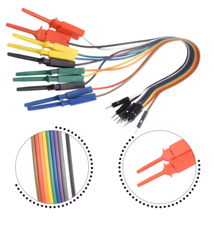
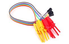
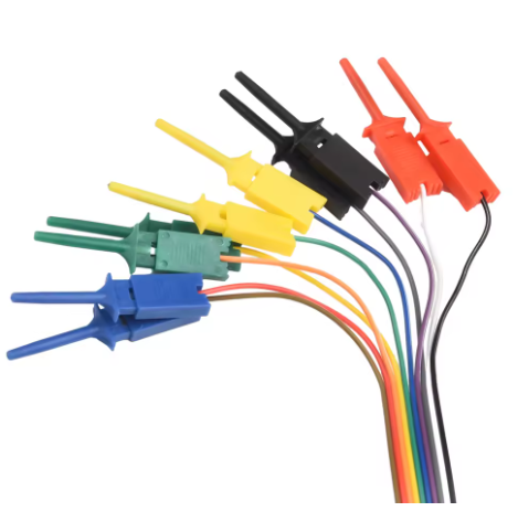
Each cable in this kit features a Dupont (2.54mm pitch) female connector on one end and a spring-loaded test hook clip on the other. The Dupont end plugs directly into the input headers of your logic analyzer or oscilloscope, while the hook clips latch onto IC pins, component leads, or even fine-pitch SMD legs . The spring mechanism ensures a secure, hands-free connection, allowing you to operate your test equipment while the hook remains firmly attached, even in tight spaces .

This set typically contains 10 wires in a bundle, which can be easily separated into individual strands. With a cable length of approximately 20–30cm (8–12 inches), they offer enough reach for complex test setups while remaining short enough to minimize signal noise and voltage drop . The 22AWG wiring standard ensures durability and reliable conductivity, making this kit an essential addition to any electronics workbench, from professional development labs to DIY hobbyist stations .

Key Features

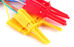
  • Spring-Loaded Test Hooks: Features a “push-to-open” plunger mechanism with a sharp, retractable hook. This design securely grips IC legs, component leads, jumper wires, and SMD pads, allowing for stable “hands-free” testing .

  • Dupont 2.54mm Female Connector: The opposite end uses a standard 2.54mm pitch Dupont female socket, offering universal compatibility with logic analyzers, oscilloscopes, USB test boards, and development boards like Arduino and Raspberry Pi .

  • Color-Coded Leads: The wires are available in multiple distinct colors. This visual differentiation helps you quickly identify assigned channels (e.g., CH0 to CH7) in your software interface, reducing wiring errors during complex debugging .

  • 20-30cm Cable Length: Optimized for bench testing—provides sufficient flexibility to connect a device under test to a USB analyzer without creating excessive cable noise or signal reflection .

  • 22AWG or 28AWG Stranded Wire: Constructed with stranded copper wire for high flexibility and resistance to breakage. Some premium variants feature silicone insulation for extreme heat resistance and ultra-soft handling .

  • 2.5mm Jaw Opening: The hook tips can open to approximately 2.5mm, allowing them to grip standard 0.1-inch (2.54mm) header pins as well as small surface-mount IC legs .

  • Easy to Split: The multi-wire ribbon cable is designed to be easily torn apart, allowing you to customize the number of channels you need (1, 2, 4, or 8) for your specific measurement task .

  • Durable Material: Metal claws are typically nickel or gold-plated to prevent corrosion and ensure long-lasting electrical conductivity, while the over-molded plastic stress relief prevents the wire from detaching at the solder joint .

Technical Specifications

Parameter Operating Value
Connector Type (Device End) 2.54mm Pitch Dupont Female Connector
Connector Type (Probe End) Spring-Loaded Test Hook (Push-to-Grab)
Jaw Opening Maximum Approx. 2.5mm
Quantity 10 wires per pack
Cable Length Approx. 200mm – 30cm (8 to 12 inches)
Wire Gauge 28AWG to 22AWG (varies by manufacturer)
Ribbon Type Multi-color flat ribbon (splittable)
Color Options Red, Black, Blue, Green, Yellow, White, etc.
Operating Temperature -40°C to +85°C
Ideal For Logic Analyzers, Oscilloscopes, JTAG Debuggers

Usage Guide

1. Standard Connection (Logic Analyzer)

  1. Prepare the Ribbon: If the wires arrive as a unified ribbon, gently pull the end to separate it into individual strands. This allows you to customize the number of probes needed for your specific task .

  2. Connect to Device: Insert the Dupont Female end into the input headers of your logic analyzer (e.g., Channels 0 through 7). Ensure a snug fit for solid contact .

  3. Attach to Target: Press the plunger on the test hook to retract the jaws. Place the exposed hook over the pin, leg of a chip, or test point. Release the plunger. The spring will pull the jaws shut, clamping firmly onto the point .

2. One Logic Analyzer Connection Guide

Logic Analyzer Channel Wire Color (Example) Target Connection Point
Channel 0 (CH0) Yellow MOSI (Master Out Slave In)
Channel 1 (CH1) Blue MISO (Master In Slave Out)
Channel 2 (CH2) Green SCK (Serial Clock)
Channel 3 (CH3) Red CS (Chip Select)
Channel 4 (CH4) Black GND (Ground Reference)

3. Troubleshooting Tips

  • Loose Connection: If the clip feels loose, you can gently squeeze the metal jaw with pliers to tighten the grip. Be careful not to break the plastic housing .

  • Broken Wire: The soldered connection between the hook and the wire can sometimes break after heavy repeated bending. Consider reinforcing the joint with a drop of hot glue or heat-shrink tubing for longevity .

Q: Can I use these grabbers with a standard 8-channel USB Logic Analyzer?

Yes. These test hooks are specifically designed for use with 8-channel USB logic analyzers. They feature a standard 2.54mm Dupont connector that plugs directly into the analyzer’s female input headers .

Q: Are these compatible with both male and female header pins?

Dupont (Female) End: The kit comes with a female socket designed to plug into male headers on your device (e.g., logic analyzers). Test Hook End: The hook is designed to grab exposed male pins, component legs, or solder points. To connect to female headers, you may need a Male-to-Male jumper wire as an adapter .

Q: What types of integrated circuit (IC) packages can this hook grab?

The standard hook works well on through-hole DIP chips, SOIC, and (with a steady hand) TSSOP leads. It is also useful for grabbing wire-wrap posts, resistor leads, and the edges of test pads. However, very fine-pitch ICs (like QFP) may require thinner micro-grabbers available on higher-end kits .

Q: How do I ensure a secure, non-slip grip on the pin?

Push the plunger completely in, place the hook so that the target pin rests inside the recessed metal jaw, and then release the plunger fully. For round pins, try to align the pin perpendicular to the jaw opening to maximize surface friction .

Q: Why does my cable look like a flat ribbon? Can I separate the wires?

Yes, definitely. These test leads come in a 10-wire flat ribbon cable to keep them organized . You can easily split the wires by hand. It is recommended to keep at least two or three wires together if you need them to run to the same area (e.g., SPI bus) to maintain neatness.

Q: What is the "push-to-grab" mechanism?

You press the plunger to open the hook, place the hook over the pin, and release. The internal spring pulls the closed hook tight, creating a hands-free connection that stays attached even if the board is moved slightly .

Q: How do I select the correct color for my specific DIY project?

It is generally best to choose high-contrast colors for your test leads. For example, a dedicated Black wire for Ground, Red for Power, and distinct colors (Yellow, Blue, Green) for data lines (MOSI, MISO, SCK) makes it much easier to trace which pin corresponds to which channel when looking at your software display .

Q: Are these usable for surface mount (SMD) component testing?

Yes, with patience. The sharp tip can fit under the small legs of SOIC chips, allowing you to clip onto the lead itself. However, they may be too bulky for 0402 passive components or 0.5mm pitch QFNs .

Q: Why am I getting intermittent signal readings on my logic analyzer?

This is usually due to a bad ground connection. You must connect a test hook from the analyzer’s “GND” pin to the common ground of your target device. Without a shared reference, the logic levels become unstable, leading to garbage data .

Q: I'm using these for flashing firmware (JTAG/SWD). Are they reliable for long periods?

Yes, the spring-loaded mechanism is designed for hands-free operation. Once clamped, the hook will stay attached securely, allowing you to execute a 5-10 minute flash process or run a long-term stability test without holding the probes yourself .