Product Overview
The 3.7V to 5V 2A Step-Up Boost Converter Board is a compact, high-efficiency power module designed to convert the nominal voltage of a single lithium-ion or lithium-polymer battery (3.7V) into a stable 5V output suitable for powering USB devices, microcontrollers, sensors, and other 5V electronics . Whether you are building a portable power bank, powering an Arduino from a single 18650 battery, or creating a battery-powered IoT sensor, this module provides the essential voltage conversion needed for reliable operation.
At its core is a high-frequency DC-DC boost converter circuit that uses an inductor, a switching transistor, and a controller IC to step up the input voltage with up to 92% efficiency . The module is designed to accept a wide input range (typically 2.5V to 5.5V) and deliver a regulated 5V output at up to 2A peak current . This makes it an ideal solution for projects where a single lithium battery must power 5V logic devices, such as Arduinos, ESP32s, and Raspberry Pi Zeros .
Key Features
-
High-Efficiency Boost Conversion: Converts a 3.7V Li-ion battery input to a stable 5V output with efficiency up to 92%, minimizing power loss and extending battery life .
-
2A Peak Output Current: Capable of delivering up to 2A of output current (peak), suitable for powering a wide range of 5V devices including microcontrollers, sensors, and USB peripherals .
-
Wide Input Voltage Range: Accepts input voltages from 2.5V to 5.5V, making it compatible with single-cell Li-ion batteries (3.0V-4.2V), 3.7V LiPo packs, and even 3.3V or 4.2V power sources .
-
Built-in Protection Features: Includes overcurrent protection (OCP), overvoltage protection (OVP), undervoltage lockout (UVLO), and thermal shutdown to safeguard both the module and your connected devices .
-
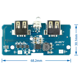
Compact and Lightweight: Small PCB footprint (typically 42mm x 15mm) with a low profile, allowing easy integration into portable projects, enclosures, and battery packs .
-
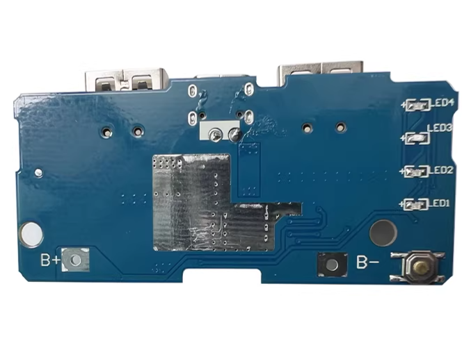
Status Indicator LED: An onboard LED provides visual confirmation of output power, making it easy to verify operation at a glance .
-
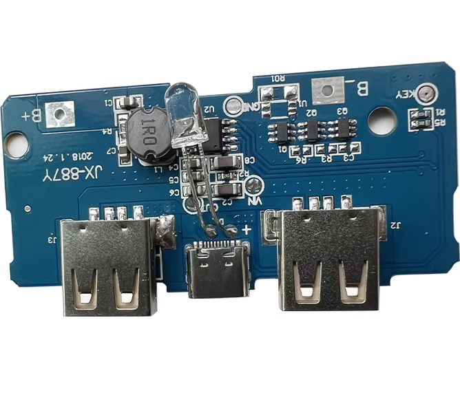
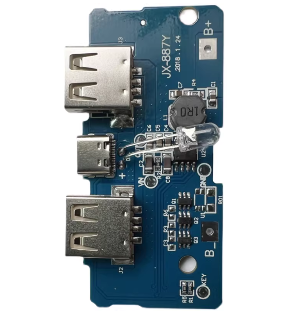
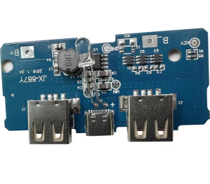
Multiple Connection Options: Equipped with a USB-A port for direct output and/or solder pads (IN+, IN-, OUT+, OUT-) for flexible wiring, enabling use with battery holders, JST connectors, or custom wiring .
-
Switch-Mode Regulator Design: Uses high-frequency switching (typically 1MHz) for high efficiency and minimal external component size, resulting in a clean, stable output with low ripple .
Technical Specifications
Pinout & Interface Guide
The module typically offers two connection options for input and output:
Input Side (Battery Connection)
Output Side (Load Connection)
-
OUT+ (VOUT): 5V regulated output. Connect to the VCC/5V pin of your device.
-
OUT- (GND): Output ground. Connect to the GND pin of your device.
-
USB-A Port: Alternatively, plug a USB device directly into the port for 5V power (where available) .
Usage Guide
Battery Selection
The module is designed for use with single-cell lithium-ion or lithium-polymer batteries with a nominal voltage of 3.7V (full charge 4.2V, cut-off around 3.0V). It is compatible with:
-
18650 battery cells
-
Flat LiPo battery packs (e.g., 502030, 602540, etc.)
-
Any 3.7V battery with sufficient current capability (typically ≥ 2A discharge rate) .
Important: Do not use multiple batteries in series (which would increase voltage) unless they are first connected in parallel (which increases capacity) .
Wiring Instructions
-
Connect the Battery: Solder the positive wire of your battery to the IN+ pad and the negative wire to the IN- pad. Ensure correct polarity—reversing connections can damage the module .
-
Connect the Load:
-
Power On: Once the battery is connected, the module will begin boosting the voltage to 5V. The onboard LED should illuminate, indicating active output.
Application Examples
-
Powering an Arduino Uno (via USB): Use a 3.7V Li-ion battery to provide 5V power to the Arduino’s USB port.
-
ESP32 / ESP8266 Projects: Power your Wi-Fi-enabled microcontroller from a single 18650 battery, ensuring 5V stability for sensors and communication .
-
Portable Power Bank: Combine this module with a 18650 battery to create a simple, DIY USB power bank for charging phones or small devices .
-
Raspberry Pi Zero: The module can supply the required 5V 2A (peak) to power a Raspberry Pi Zero from a Li-ion battery .
Important Considerations
-
Current Capacity: While rated for 2A peak, the continuous output current may be lower depending on the input voltage, the quality of the battery, and the module’s thermal environment . For sustained high-current loads (≥1.5A), ensure good airflow and use a high-quality battery with a sufficient discharge rate.
-
Inductive Loads: When powering motors or other inductive loads, the module may experience transient voltage dips. Adding a large electrolytic capacitor (100-470µF) across the output can help stabilize the voltage.
-
Heat Dissipation: Under heavy load (near 2A), the module may become warm. Ensure adequate ventilation and avoid enclosing it in a sealed, non-ventilated space.
-
Battery Protection: Although the module includes undervoltage protection, it is highly recommended to use a battery with a built-in protection circuit (PCM) to prevent over-discharge and extend battery life .
Q: What is the purpose of a boost converter?
A boost converter steps up a lower input voltage to a higher output voltage. In this case, it converts a 3.7V Li-ion battery’s voltage (which can range from 3.0V to 4.2V) into a stable 5V, which is required by many electronics like Arduinos, ESP32s, and USB devices
Q: What is the maximum current I can draw from this module?
The module is rated for 2A peak output current. However, the sustainable continuous output is typically around 1.5A. The actual achievable current depends on your input voltage (lower battery voltage reduces current capacity), the quality of your battery, and the module’s temperature
Q: Can I use this module to charge my battery?
No. This module is a boost converter only. It takes power from the battery to create 5V. It does not have a charging circuit to safely charge a Li-ion battery. To charge the battery, you need a separate lithium battery charger module (e.g., TP4056)
Q: Can I use this module with a 5V USB power supply as the input?
Yes, you can technically use a 5V USB supply as input. However, if the input is already 5V, a boost converter is unnecessary. The module would still output 5V, but there would be little benefit, and you would be adding an extra, unnecessary conversion stage.
Q: Can I connect multiple batteries in parallel for longer runtime?
Yes. You can connect multiple 3.7V Li-ion batteries in parallel (positive to positive, negative to negative). This will increase the total capacity (mAh) and runtime without increasing the voltage. However, you should ensure the batteries are at the same voltage level before connecting them
Q: Why does the output voltage drop when I connect a high-current device?
This can be caused by:
-
The battery voltage dropping under load (voltage sag). Use a high-quality battery with a good discharge rate.
-
The battery’s state of charge being low (below 3.5V).
-
The load exceeding the module’s maximum current capability. The module will go into current limiting, causing the voltage to drop
Q: The module gets hot when running a motor. Is this normal?
The module will generate some heat under load, especially when delivering 1-2A. If it becomes too hot to touch (above 70°C), you may be exceeding its current rating or the ventilation is inadequate. For high-current loads, consider adding a heatsink or using a fan.
Q: How efficient is this module?
The module can achieve up to 92% efficiency under optimal conditions (input around 3.7V, output at 1-1.5A) . This means only about 8% of the power is lost as heat, which is excellent for a compact boost converter.
Q: What is the quiescent current when nothing is connected?
The module typically consumes less than 80µA in standby, which is very low. However, if you have an LED indicator or other components always on, the consumption will be higher. For battery-powered projects, consider adding a physical power switch to completely disconnect the battery when not in use.
Q: The output LED is off and there is no 5V output. What should I check?
Follow this checklist:
-
Check the Battery: Is the battery voltage above 2.8V? Use a multimeter to measure the voltage at the IN+ and IN- pads. If the battery is below the undervoltage lockout threshold, the module will not turn on.
-
Check Polarity: Ensure the battery is connected with correct polarity (positive to IN+, negative to IN-). Reversing polarity can damage the module.
-
Check Connections: Solder joints should be solid. Loose connections can interrupt power delivery.
-
Check Load: Disconnect the load and see if the LED turns on. A short circuit on the output can cause the module to shut down.
Q: The module was working, but it suddenly stopped. What happened?
The module likely went into a protection mode due to:
-
Overcurrent: The load drew more than 2A.
-
Overtemperature: The module overheated.
-
Undervoltage: The battery voltage dropped below the safe operating level.
Allow the module to cool, recharge the battery, and try again. Ensure the load is within the module’s specifications.
Q: Can I use this module to power a 12V device?
No. This specific module outputs a fixed 5V. To boost to 12V, you would need a different boost converter designed for a higher output voltage, such as an MT3608-based module
Q: Can I use this module while the battery is charging?
It is not recommended to simultaneously charge a battery with a separate charger and use this module to draw power from the battery. A dedicated power management IC (like the IP5306) is required for proper power path management . A simple charger and boost converter combination may cause unstable operation or battery damage.