Product Description
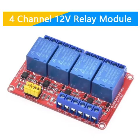
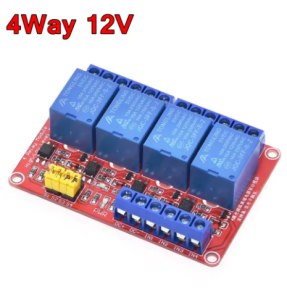
The 4 Channel 12V Relay Module with Optocoupler is a professional-grade interface designed to deliver reliable, isolated control for 12V-based automation and industrial systems. This module provides a robust and secure bridge between 12V logic signals from controllers, PLCs, or automotive systems and a variety of high-power AC or DC loads. Its defining feature is the integration of advanced optocouplers on all four channels, creating a critical 2500V electrical isolation barrier that completely separates sensitive control electronics from potentially noisy, high-voltage load circuits. This protection ensures immunity from damaging voltage spikes, ground loops, and electromagnetic interference, guaranteeing the stability and longevity of your control equipment.
Engineered for maximum versatility, the module features individually selectable high-level or low-level trigger logic for each channel via simple jumpers, offering seamless compatibility with any 12V control signal type. Combining four high-current relay outputs, clear per-channel status indicators, and secure screw terminal connections, this module is the ideal solution for building reliable multi-circuit control systems, industrial machine interfaces, and complex automation projects where safety, signal integrity, and flexible integration are essential.
Key Features
-
Quad-Channel Opto-Isolation: All four independent channels are protected by individual optocouplers, providing 2500Vrms of isolation to shield your 12V controller from hazardous load-side transients and electrical noise.
-
Dual Trigger Logic Selectable: Each channel can be individually configured for High-Level (active on +12V) or Low-Level (active on 0V/GND) trigger via a jumper, ensuring compatibility with all 12V sourcing (PNP) or sinking (NPN) control outputs.
-
Industrial 12V DC Compatibility: Designed for direct integration into standard 12V industrial, automotive, and control system environments without requiring additional logic level conversion.
-
High-Power Relay Outputs: Features four robust electromagnetic relays with SPDT contacts, each capable of switching loads up to 10A at 250VAC or 30VDC for versatile application use.
-
Clear Operational Feedback: Dual LEDs per channel provide immediate visual diagnostics: one indicates opto-isolator input status, and the other confirms physical relay activation and contact closure.
-
Secure & Robust Connections: All high-current load and DC power inputs utilize reliable screw terminals, ensuring safe and vibration-resistant wiring suitable for demanding installations.
-
Integrated Flyback Protection: Each relay coil includes a protection diode to suppress inductive voltage spikes when de-energized, safeguarding the driving circuitry and enhancing overall reliability.
-
Compact & Efficient Design: Optimized PCB layout provides four fully isolated relay channels in a compact, easy-to-install form factor for space-conscious control panels and enclosures.
Main Parameters
-
Channels: 4 Independent Relays
-
Control & Logic Voltage: 12V DC
-
Trigger Mode: High or Low Level (Jumper Selectable per channel)
-
Isolation Voltage: 2500V RMS (Optocoupler)
-
Relay Contact Rating: 10A @ 250VAC / 10A @ 30VDC
-
Relay Type: Electromagnetic, SPDT (Single Pole Double Throw)
-
Input Current (per channel): ~5-10mA (to activate optocoupler)
-
Dimensions: Approx. 120mm x 75mm x 22mm
Typical Applications / Usage
-
Industrial Control Interfaces: Safely connect 12V PLC or microcontroller outputs to control multiple actuators, solenoid valves, motor starters, and indicator lights in factory automation and machinery.
-
Automotive & Marine System Control: Build custom control units for vehicles or boats to manage auxiliary lighting, winches, pumps, and other 12V accessories from a central controller or switch panel.
-
HVAC & Building Automation: Control multiple zones of fans, dampers, or heaters in commercial or residential building management systems using a 12V automation controller.
-
Agricultural & Environmental Control: Automate various equipment such as irrigation valves, ventilation fans, or greenhouse lighting in agricultural setups with a 12V timer or controller.
-
Telecommunications & Security Systems: Manage power distribution, backup systems, or alarm devices in 12V-based telecom racks or security system control panels.
-
Prototyping & Development: An essential tool for engineers and developers creating prototypes for industrial controls, test equipment, or custom 12V automation solutions.
Connection & Configuration Guide:
-
Trigger Configuration: For each channel, place the jumper cap over the pins labeled “H” for High-Level trigger (activates on +12V signal) or “L” for Low-Level trigger (activates on 0V signal) to match your controller’s output type.
-
Power & Control Wiring: Connect a stable 12V DC power supply to the module’s VCC and GND terminals. Connect the four signal input pins (IN1 to IN4) to the digital outputs of your 12V controller (PLC, microcontroller, etc.).
-
Load Wiring: For each channel, connect the power source (AC mains or DC supply) to the relay’s Common (COM) terminal. Connect the device to be controlled to the Normally Open (NO) terminal to be powered when the relay activates, or to the Normally Closed (NC) terminal for alternative logic.
-
Critical Safety: Always disconnect all high-voltage AC mains or high-current DC power before making or changing any load-side connections. Install the module in a properly rated, insulated enclosure and follow all applicable electrical safety codes and standards.
Q: Why is optical isolation important for a 12V relay module?
Optical isolation creates a complete electrical barrier between the control circuit (your 12V controller) and the load circuit (potentially high-voltage/current devices). This prevents damaging voltage spikes, ground loop currents, and electrical noise generated by motors, solenoids, or AC switching from interfering with or damaging your sensitive control electronics.
Q: My controller has 24V outputs. Is this 12V module compatible?
No, it is not directly compatible. Applying 24V to the control inputs or the VCC pin will damage the optocouplers and other components. You need a module specifically designed for 24V control logic or must use a voltage regulator to step down the 24V to 12V for the module’s inputs.
Q: How do I choose between High-Level and Low-Level trigger mode?
The choice depends on your controller’s output configuration:
-
High-Level (H): Use when your controller provides +12V on its output pin to activate the relay (typical of “sourcing” or PNP outputs).
-
Low-Level (L): Use when your controller connects the output pin to ground (0V) to activate the relay (typical of “sinking” or NPN outputs).
Consult your controller’s documentation to determine its output type.
Q: What power supply do I need for this module?
You need a stable 12V DC power supply. The main power consumption comes from the relay coils. Each 12V relay coil draws approximately 80-100mA when activated. If all four relays are energized simultaneously, ensure your 12V supply can provide at least 400mA of continuous current, plus additional capacity for your controller if powered from the same source.
Q: Can I use one channel to control a 3-phase motor or a large water heater?
No, not directly for high-power devices. The relays are rated for 10A. High-power devices like water heaters often draw more current. For 3-phase motors, you need to switch all three phases simultaneously. The correct and safe method is to use one channel of this module to control the coil of a suitably rated contactor or motor starter, which is designed to handle the high-power load.
Q: One channel's opto-isolator LED is on, but the relay doesn't click or switch. What's wrong?
This typically indicates an issue with power to the relay coils. The opto LED is powered from the control signal, but the relay coil requires sufficient current from the module’s main 12V power supply (VCC). Ensure your 12V supply is connected, provides adequate current, and is functioning properly.
Q: Can I mix different voltages on the load side of the four channels?
Yes. Each relay’s contacts are completely independent and isolated from the others. You can safely switch different voltages and types of loads (e.g., 120VAC on channel 1, 24VDC on channel 2) on separate channels, as long as you do not exceed the individual relay’s voltage and current ratings.
Q: Is this module suitable for business, OEM, or industrial use?
Absolutely. Its industrial-grade specifications—including 12V compatibility, optical isolation, robust relay ratings, and flexible triggering—make it an excellent, reliable component for integration into commercial products, industrial control panels, vehicular systems, and OEM equipment. We offer volume pricing and can discuss custom requirements for qualified business clients. Please contact our sales team for more information.