Product Overview
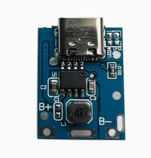
The 5V Boost Board Lithium Battery Charging Protection Board is a compact, highly integrated power management module designed for single-cell lithium batteries. Based on the 134N3P power management IC, this board combines battery charging, 5V boost output, and comprehensive protection circuits into a single, easy-to-use module—making it an all-in-one solution for DIY power banks, portable chargers, and other battery-powered projects .
This module is a major step up from simpler charger boards like the TP4056. While the TP4056 only handles charging, the 134N3P board intelligently manages the entire power flow: it charges your battery when you plug in a Type-C power source and boosts the battery’s 3.7V to a stable 5V for powering USB devices when disconnected . It automatically switches between grid power and battery power without any manual intervention.
At its core, a built-in battery protection circuit safeguards against overcharging, over-discharging, short circuits, and overheating . Indicator LEDs provide visual feedback for charging and discharging status, and the module supports trickle charging for deeply depleted batteries, reviving cells that have dropped to dangerously low voltages .
This board is the perfect foundation for making portable power banks, replacing outdated charger circuits in small electronics, or building custom battery-powered Raspberry Pi and Arduino projects. Whether you are a hobbyist or looking for a convenient OEM solution for a product design, this module provides a reliable, integrated power management core.
Key Features
-
Integrated Charge & Boost Management: All-in-one IC (134N3P) handles both 1A charging (Type-C input) and 1A 5V boost output (USB-A port) .
-
Comprehensive Protection Circuits: Includes overcharge, over-discharge (cutoff at 2.9V), overcurrent, output short circuit, overload, and over-temperature protection .
-
Smart Charging Indicator: Visual status display with red LED flashing during charging, red LED solid when fully charged, and blue LED flashing when discharging .
-
Trickle Charge Support: Can safely recharge batteries that have been over-discharged to extremely low voltages (zero voltage charging support) .
-
Low Standby Current: Consumes an ultra-low 8µA typical quiescent current when idle, minimizing battery drain when not in use .
-
85% Conversion Efficiency: High-efficiency boost converter delivers an 85% efficiency rate (at 3.7V input, 5V/1A output) for effective power utilization .
-
Built-in Power MOS: Internally installed charging and discharging power MOS reduces external component count .
-
Compatible Battery Types: Designed for single-cell 3.7V lithium batteries (Li-ion or LiPo), including 18650, 14500, and pouch cells .
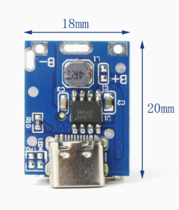
Technical Specifications
Usage Guide
Basic Wiring Instructions
IMPORTANT: This module has NO reverse polarity protection. Connecting the battery backward will instantly destroy the module. Always double-check polarity before soldering .
-
Prepare the Battery: Select a single 3.7V lithium battery (e.g., 18650). If you need more capacity, you can connect multiple batteries in parallel (B+ to B+, B- to B-). Do not connect them in series.
-
Connect Battery: Solder the positive wire of your battery to the B+ pad. Solder the negative wire to the B- pad. Ensure there is proper insulation between the battery and the circuit board when installing .
-
First-Time Activation: After connecting the battery, do not use it immediately. Plug a Type-C cable into the board and connect it to a charger. Let it charge until the battery is full. This “priming” step is important for the IC to initialize correctly and ensure that it starts and shuts down accurately .
-
Use Power Bank: Once activated, you can disconnect the charger. The blue LED should flash at intervals, and the USB-A output will now be active, allowing you to charge external devices.
Understanding the LEDs
The module uses LED indicators to show its operating status :
Battery Percentage Display (If Included)
For modules that include a 4-LED battery indicator, the percentage shown may not be perfectly accurate, especially for old or new batteries. The common way to calibrate the reading is to fully charge the device, then use it until it automatically turns off, and then fully charge it again .
Important Usage Notes
-
Output Current Limitation: The maximum output current is 1A . This module is designed for low-to-medium power devices. It is not suitable for high-current applications.
-
Parallel Batteries for Capacity: To increase the total runtime (mAh), you must connect batteries in parallel (positive to positive, negative to negative). Connecting them in series will increase voltage and destroy the module.
-
Reverse Polarity Warning: This is the single most common point of failure. Connecting the battery with reversed polarity will instantly and permanently damage the IC .
-
Output is Load-Dependent: The 1A output rating is the maximum; the module automatically adjusts the output current based on the connected USB load .
Q: What is the difference between this 134N3P module and a TP4056 charger?
A TP4056 is only a charger. It can charge a battery from USB, but you need a separate boost converter to get 5V out of the battery. The 134N3P is a complete power management system that integrates both charging and 5V boosting functions in one module, plus automatic power path management .
Q: Can I use this module to charge a battery and power a device at the same time?
Yes. The module supports a “power path” and will power a load from the USB input if available. However, the total current output (charging the battery + powering the load) is limited by the input source. If the load draws too much current, the battery may not charge effectively .
Q: Does this module provide battery low voltage cutoff?
Yes. The protection circuit monitors the battery voltage continuously. If it drops to approximately 2.9V, the output (USB-A port) will be automatically switched off to prevent the battery from being over-discharged and permanently damaged .
Q: Is reverse polarity protection included?
NO. This is a critical safety warning. This module does NOT have reverse polarity protection. Connecting the battery backward will instantly and permanently destroy the 134N3P IC . Always double-check your connections.
Q: Can I use a 12V power supply as an input?
No. The maximum input voltage is 5.5V DC. Applying 12V will destroy the 134N3P chip. You must use a standard 5V USB charger .
Q: My module doesn't work after I soldered it. What should I check?
Follow this checklist:
-
Check Polarity: Immediately check if the battery was connected backwards. If so, the IC is likely damaged .
-
Check Connections: Ensure the battery is properly soldered to the B+ and B- pads with no cold solder joints or shorts.
-
Prime the IC: Did you follow the “first-time activation” step? Connect it to a charger to “prime” the system .
Q: Why is my battery not getting fully charged to 4.2V?
The module is designed to charge to 4.2V with ±1% accuracy . If it seems to stop early, the battery might be old or damaged, or the connections may have high resistance.
Q: The LED display shows the wrong battery percentage. How to fix it?
The battery indicator circuit measures voltage, which is an indirect method of estimating capacity and can be inaccurate. Calibrate the reading by fully charging and discharging the battery a couple of times .
Q: What can I build with this 134N3P power module?
Popular applications include:
-
DIY Power Bank: Build your own compact portable charger using an 18650 battery .
-
Portable Arduino/Raspberry Pi Project: Power your project from a single 18650 battery.
-
Rechargeable LED Light: Create a bright, portable work light that charges from USB.
-
Battery Upgrade for Electronics: Replace non-rechargeable batteries in small devices with a rechargeable Li-ion setup.
Q: Can I run a DC motor directly from this module's USB output?
Generally not recommended. DC motors have very high inrush currents when starting up. This surge will likely exceed the 1A output limit and trigger the protection circuitry, causing the module to shut down . If you need to run a motor, power it directly from the battery.
Q: What is the recommended way to connect multiple cells for higher capacity?
The cells must be connected in parallel. Solder all positive terminals together (B+) and all negative terminals together (B-). The batteries should be at the same voltage before connecting them to prevent a large, damaging current flow between them. Do not connect batteries in series.