Product Overview
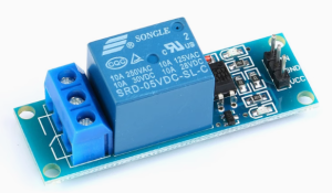
The 5V Single Channel Optocoupler Isolated Relay Module is a high-performance, ready-to-use control module that allows your low-voltage microcontroller (such as Arduino, ESP32, or Raspberry Pi) to safely and reliably switch high-power AC or DC loads. Whether you’re controlling home appliances, motors, or industrial equipment, this module provides a robust interface between your 5V logic and the high-voltage world .
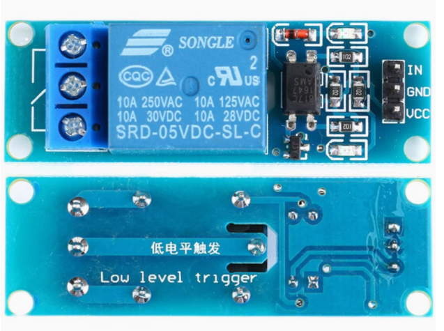
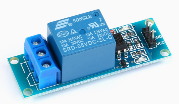
At its core is a high-quality electromagnetic relay capable of switching loads up to 10A at 250V AC or 10A at 30V DC. The module features optocoupler isolation, which creates a physical and electrical barrier between your sensitive control circuit and the potentially hazardous load side. This isolation protects your microcontroller from dangerous voltage spikes, back-EMF from motors, and electrical noise .
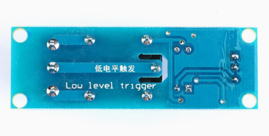
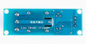
Designed with a low-level trigger, this module is activated when you apply a LOW signal (0V) to the input pin. This default behavior ensures that the relay remains off during power-up or microcontroller reset, preventing accidental activation of connected devices . An onboard status LED provides clear visual confirmation of relay operation, and the module’s compact design allows for easy integration into breadboards, enclosures, or custom PCBs.
Key Features
-
Optocoupler Isolation: Provides complete electrical isolation between the control side (5V logic) and the load side (up to 250V AC), protecting your microcontroller from voltage spikes and electrical noise .
-
High Load Capacity: SPDT relay contacts rated for 10A at 250V AC or 10A at 30V DC, suitable for controlling lights, fans, pumps, solenoids, and small motors .
-
Low Level Trigger: The relay activates when the IN pin is pulled LOW (0V). This “active LOW” behavior is designed for safety—the relay remains off during power-up or if the control signal is lost .
-
Clear Status Indicators: Onboard LEDs provide visual feedback: a power LED (typically green) lights when the module is powered, and a relay status LED (typically red) illuminates when the relay is activated .
-
SPDT Contact Configuration: Provides Common (COM), Normally Open (NO), and Normally Closed (NC) terminals for flexible wiring options. Use NO for devices that should be OFF by default, or NC for devices that should be ON by default .
-
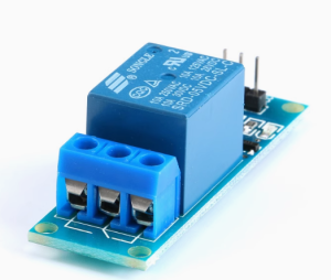
Easy 3-Pin Control Interface: Standard 2.54mm pitch header for VCC (5V), GND, and IN (control signal) allows direct connection to breadboards and microcontrollers .
-
Compact and Durable: Small form factor with mounting holes for secure installation. The isolation slot between control and load areas enhances safety .
-
Wide Compatibility: Works with 5V logic from Arduino, and can be controlled by 3.3V microcontrollers like ESP32 or Raspberry Pi with proper level considerations .
Technical Specifications
Pinout & Interface Guide
Input Side (Control Interface)
Output Side (Load Terminals)
Status LEDs
Usage Guide
Wiring Instructions
IMPORTANT: Always disconnect mains power before wiring high-voltage loads.
Basic Connection (Control Side)
Load Connection (AC Example)
-
Connect the Live (L) wire from your AC source to the COM terminal
-
Connect the load (lamp, fan, etc.) to the NO terminal
-
Connect the load’s Neutral (N) wire directly to the AC source neutral
Load Connection (DC Example)
-
Connect the positive (+) supply to the COM terminal
-
Connect the load’s positive wire to the NO terminal
-
Connect the load’s negative wire directly to the power supply ground
Control Logic
Since this module is low-level triggered, the relay behavior is as follows:
Example Arduino Code
const int relayPin = 7;
void setup() {
pinMode(relayPin, OUTPUT);
digitalWrite(relayPin, HIGH);
}
void loop() {
digitalWrite(relayPin, LOW);
delay(5000);
digitalWrite(relayPin, HIGH);
delay(5000);
}
Example MicroPython Code (Raspberry Pi Pico / ESP32)
from machine import Pin
import time
relay = Pin(7, Pin.OUT)
relay.value(1)
while True:
relay.value(0)
time.sleep(5)
relay.value(1)
time.sleep(5)
Important Considerations
-
Power Supply: The module requires a stable 5V DC supply capable of providing at least 100mA (the relay coil draws approximately 65-80mA when active) .
-
3.3V Microcontrollers: When using 3.3V logic (ESP32, Raspberry Pi Pico), the LOW signal (0V) works as expected, but ensure the HIGH signal (3.3V) is sufficient to turn the relay off (it typically is, as the threshold is around 2V) .
-
Inductive Loads: For motors, pumps, or solenoids, add a flyback diode across the load to protect the relay contacts from voltage spikes.
-
Default State: The low-level trigger design means the relay stays OFF when the microcontroller pin is HIGH or unconfigured, preventing unwanted activation during power-up
Q: What is the difference between low-level trigger and high-level trigger?
Low-level trigger means the relay activates when the IN pin is pulled LOW (0V). High-level trigger means the relay activates when the IN pin is HIGH (5V). This module is low-level trigger, which is safer because the relay remains off during power-up or if the control signal is lost
Q: What is the maximum load this relay can handle?
The contacts are rated for 10A at 250V AC or 10A at 30V DC. For inductive loads like motors, it is recommended to derate to 5A–7A to account for startup surges
Q: What is the purpose of the optocoupler?
The optocoupler provides electrical isolation between the control circuit (your microcontroller) and the high-voltage load. This protects your sensitive electronics from voltage spikes, back-EMF, and electrical noise
Q: Can I use this relay with a 3.3V microcontroller like ESP32 or Raspberry Pi Pico?
Yes. The module is designed for 5V logic, but a 3.3V microcontroller can still control it. The LOW signal (0V) works perfectly. For the HIGH signal (3.3V), the relay will typically turn off reliably since the threshold is around 2V
Q: What power supply do I need for this module?
The module requires a stable 5V DC power supply capable of providing at least 100mA. The relay coil draws approximately 65-80mA when active, plus a small quiescent current
Q: Why does the relay click but my load doesn't turn on?
This indicates the relay is activating but the load circuit is incomplete. Check:
-
The load is correctly wired between COM and NO (or COM and NC, depending on desired behavior)
-
The load’s neutral/ground is connected correctly
-
The load itself is functional
-
The load’s current does not exceed the relay’s 10A rating
Q: The relay clicks when I power on my Arduino. Why?
During power-up, microcontroller pins may briefly float or be in an undefined state. With a low-level trigger module, this should not activate the relay because the pin needs to be pulled LOW. However, adding a 10kΩ pull-up resistor on the IN pin to 5V can ensure the relay remains OFF during startup
Q: What is the expected lifespan of this relay?
The relay is rated for approximately 10 million mechanical operations (no load) and 100,000 electrical operations at rated load. Actual lifespan depends on switching frequency and load type.
Q: Can I use this relay for 220V AC applications?
Yes. The contacts are rated for 250V AC, which is suitable for 220V/240V systems. Ensure proper insulation and clearance between the control and load sides for safety
Q: The module's status LED lights up but the relay doesn't click. What's wrong?
The LED indicates the control signal is reaching the optocoupler. If the relay doesn’t click, check:
-
The VCC power supply is stable at 5V
-
The power supply can provide enough current (at least 100mA)
-
The relay itself may be faulty (though rare)
Q: Can I use multiple relay modules with a single microcontroller?
Yes. Connect each module’s VCC and GND in parallel to the same 5V supply (ensure the supply can handle the total current), and connect each IN pin to a separate digital output pin on your microcontroller.
Q: What can I build with this relay module?
Popular applications include:
-
Home automation (lights, fans, appliances)
-
Industrial equipment control
-
IoT projects with ESP32 or Arduino
-
Remote power switching
-
Motor and pump control
-
Security systems and alarms
Q: Can I control this relay from a Raspberry Pi?
Yes. Connect the module’s VCC to 5V, GND to GND, and IN to any GPIO pin. Use the RPi.GPIO library to control the pin. Note that Raspberry Pi GPIO pins are 3.3V, which works for low-level triggering—just ensure the HIGH signal (3.3V) is sufficient to turn the relay off
Q: Is this module suitable for controlling a motor or pump?
Yes, with derating. For inductive loads like motors, it is recommended to operate at 50–70% of the rated contact current (5A–7A) to account for startup surges. Adding a flyback diode across the load is highly recommended to protect the relay contacts
Q: Can I use this module without a microcontroller?
Yes. You can trigger the relay by manually connecting the IN pin to GND (to activate) or leaving it disconnected (to deactivate). This can be done with a simple push button or toggle switch.