Description
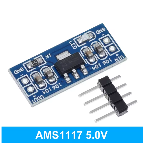
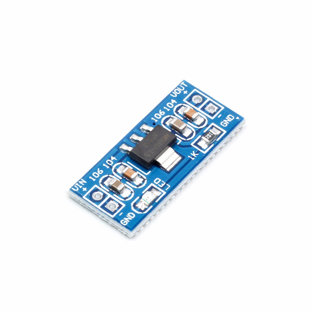
The AMS1117 5V Power Supply Module is a compact and highly efficient linear voltage regulator module designed to provide a stable and clean 5V DC output from a higher voltage DC input. Built around the renowned AMS1117-5.0 low-dropout regulator (LDO), this module is an essential building block for countless electronics projects, microcontroller applications, and prototype development.
The AMS1117 series is a popular family of low-dropout linear regulators known for their simplicity, reliability, and excellent performance. This fixed 5V version accepts a wide input voltage range (typically 6.5V to 15V DC) and steps it down to a precise 5V output with a maximum current of up to 800mA to 1A (depending on cooling and input voltage conditions) . The module features a very low dropout voltage—the minimum difference required between the input and output for proper operation—of approximately 1.1V to 1.3V at full load . This allows you to power your 5V circuits from common 7.5V to 12V wall adapters, 9V batteries, or other DC sources.
The onboard AMS1117-5.0 integrates essential protection features, including over-current protection (current limiting) and thermal shutdown, safeguarding your downstream circuitry and the regulator itself from damage during fault conditions . The regulator’s output voltage is trimmed for high accuracy, typically within ±1% to ±1.5% of the ideal 5V .
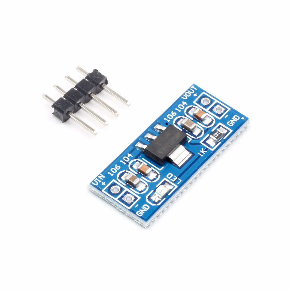
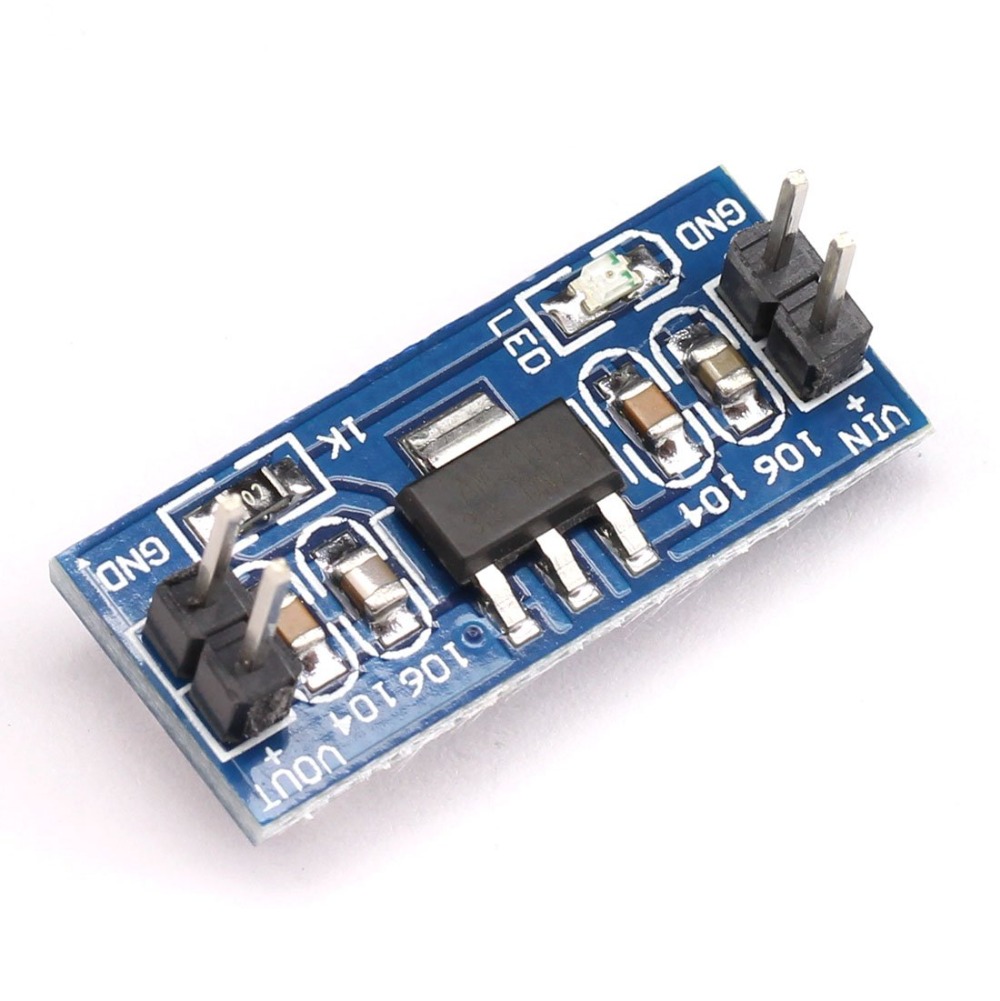
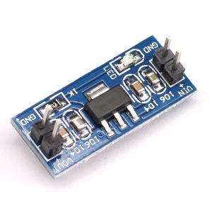
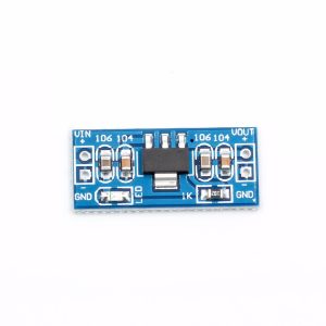
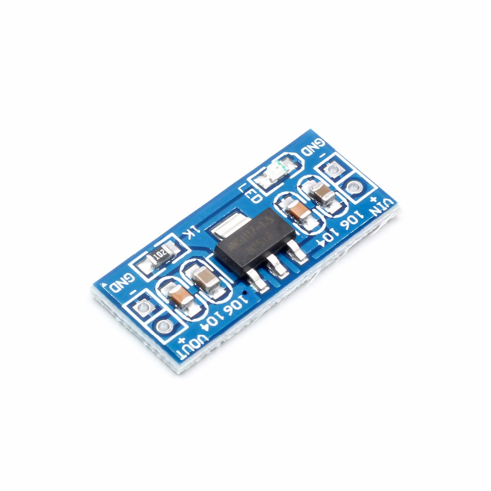
This module simplifies the use of the AMS1117 by breaking out the three essential pins (Input, Ground, Output) to easy-to-use screw terminal blocks or pre-soldered pin headers. Often, a power indicator LED is included to visually confirm that the output is active. Many variants also feature mounting holes, allowing for secure attachment within your project enclosure.
The board is typically designed with a very simple and straightforward layout, requiring only input and output filtering capacitors (often included on the module) for stable operation. This makes it an ideal “plug-and-play” solution for developers who need a reliable 5V rail without designing a custom power supply circuit.
Whether you need to power a 5V microcontroller (like Arduino Uno or Nano), a sensor module, a servo, a motor driver, or simply create a dedicated 5V test point on your workbench, the AMS1117 5V Power Supply Module provides a simple, effective, and reliable solution for all your voltage regulation needs.
Key Features
-
Fixed 5V Output – Provides a stable, regulated 5V DC output perfect for Arduino, sensors, servos, and 5V logic circuits .
-
Wide Input Voltage Range – Accepts DC inputs from 6.5V to 15V, making it compatible with 7.5V, 9V, and 12V adapters and batteries .
-
High Output Current – Capable of delivering up to 800mA to 1A of continuous output current (depending on input/output voltage differential and thermal management) .
-
Low Dropout Voltage – Requires only a 1.1V to 1.3V difference between input and output to maintain regulation, allowing it to run efficiently from 6.5V inputs .
-
Integrated Protection – Features built-in over-current limiting and thermal shutdown protection for reliable, fail-safe operation .
-
Excellent Regulation – Delivers precise output with a typical line regulation of 0.2% and load regulation of 0.4% .
-
Low Quiescent Current – Consumes a very low operating current (5-10mA), making it suitable for power-sensitive applications .
-
Easy to Use – Simple 3-pin interface (Input, Ground, Output) available on screw terminals or pin headers for quick, solderless wiring.
-
Visual Indicator – Onboard power LED provides instant visual confirmation that the module is powered and the output is active.
-
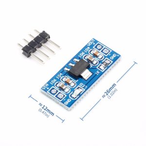
Compact Form Factor – Small footprint, typically around 25mm x 20mm, ideal for space-constrained projects and breadboard integration.
Technical Parameters
Usage Guide
How It Works
The AMS1117 is a classic low-dropout linear regulator. It operates by using a control loop to adjust the resistance of an internal power transistor. This transistor acts like a variable resistor, dropping the excess input voltage and dissipating it as heat to maintain a constant, stable 5V at the output pin . The module is ready to use; simply provide a suitable DC input voltage on the designated input terminal, and the regulated 5V output will be available on the output terminal.
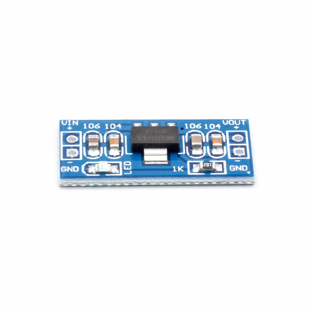
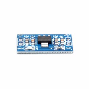
Pinout and Connections
The module provides access to all three pins of the AMS1117 regulator. While the labeling and arrangement may vary by manufacturer, the functions are universal.
Typical Wiring Diagram:
-
Connect Input Power: Attach the positive terminal (+) of your DC power supply (e.g., 9V battery, 12V adapter, or 7.5V supply) to the IN terminal.
-
Connect Ground: Attach the negative terminal (-) of your power supply to the GND terminal.
-
Connect Your Load: Attach the positive (VCC) wire of your 5V device (e.g., Arduino, sensor, servo, or logic circuit) to the OUT terminal.
-
Complete the Load Circuit: Connect the ground (GND) of your 5V device to the GND terminal on the module.
Important Usage Considerations
Input Voltage (VIN)
-
Minimum Input: For stable operation at the full 800mA output, the input voltage must be at least VOUT + Dropout Voltage, or approximately 6.5V . A 7.5V to 9V supply is a common and efficient choice.
-
Maximum Input: The absolute maximum input voltage is 15V . Exceeding this can permanently damage the regulator. For 12V inputs, ensure adequate heat dissipation.
-
Efficiency & Heat: An LDO like the AMS1117 is not 100% efficient. The wasted power is calculated as (VIN - VOUT) × ILOAD and is dissipated as heat. For example, with a 12V input and a 500mA load, the module must dissipate (12V - 5V) × 0.5A = 3.5W of heat. At higher currents and voltages, the module will become very hot.
Output Current (IOUT)
-
The theoretical maximum current is 1A . However, the practical safe current is less and depends heavily on how much heat the module can dissipate. For a 12V input, it is recommended to keep the load well under 500mA to prevent overheating.
-
For high-current applications at higher voltages, a switching (buck) converter is a much more efficient solution.
Power Indicator LED
Heat Management
The AMS1117 can get hot, especially when converting a high voltage (e.g., 12V) to 5V at a moderate current . Consider the following:
-
Test Before Enclosing: Always test your circuit and feel the temperature of the regulator IC. If it is too hot to touch comfortably, you need to reduce the current, lower the input voltage, or add a heat sink.
-
Heat Sinking: The regulator’s metal tab is often connected to ground. You can glue or solder a small stick-on heat sink to this tab to improve cooling.
-
PCB Design: For custom boards, providing a generous area of copper connected to the regulator’s ground pin can help wick away heat.
Typical Applications
Q: What is the minimum input voltage to get a stable 5V output?
The AMS1117-5.0 has a dropout voltage of approximately 1.1V to 1.3V at full current. This means the input must be at least 6.1V to 6.3V . For reliable operation, a 7.5V to 9V supply is the most common and efficient choice, providing a comfortable 2.5V to 4V of headroom.
Q: Can I power this module from a 5V USB supply?
No. To get a stable 5V output, you need an input voltage higher than 5V. The AMS1117 requires at least 6.1V to 6.3V to regulate properly. If you supply 5V to the input, the output will be approximately 5V minus a small drop, but it will not be regulated and will fluctuate with the load. For 5V to 5V conversion, you would not use a regulator at all; you would connect directly.
Q: Why is my AMS1117 module getting extremely hot?
This is the most common issue with linear regulators. The heat is the result of wasted power being dissipated. Use the formula: Power = (VIN – VOUT) × ILOAD .
-
Example: With VIN = 12V, VOUT = 5V, and ILOAD = 500mA, the power dissipated is (12 - 5) × 0.5 = 3.5W. This is a significant amount of heat for a small SOT-223 package.
-
Solutions: Reduce the input voltage (use 7.5V or 9V instead of 12V), reduce the current draw of your load, or attach a small heatsink to the regulator’s tab. For high-current or high-voltage-difference applications, a switching buck converter is recommended.
Q: What is the maximum current I can draw from this module?
The AMS1117 chip is rated for a maximum of 800mA to 1A . However, the practical limit depends on the input voltage and cooling. With a 7.5V input and good airflow, you can reliably draw 600-800mA. With a 12V input, you should limit the current to 200-300mA to prevent overheating .
Q: What are the "IN", "GND", and "OUT" terminals on the module for?
-
IN (Input): This is where you connect your unregulated higher voltage power source (e.g., +7.5V, +9V, or +12V).
-
GND (Ground): This is the common ground reference for both the input and output. You must connect the ground of your power source and the ground of your load to this terminal.
-
OUT (Output): This is the regulated 5V output. You connect the positive power input of your 5V device (Arduino, sensor, servo, etc.) to this pin.
Q: Can I use this module to power an Arduino from a 12V supply?
Yes, absolutely! This is one of the most common use cases. Most Arduino boards (like Uno, Nano, and Mega) have their own onboard 5V regulator, but it can get hot when powered from 12V, especially if the Arduino is also powering many sensors or LEDs. Using an external AMS1117 5V module to power the Arduino’s 5V pin is an excellent way to offload the heat from the Arduino’s own regulator.
Wiring: Connect 12V to the module’s IN, module’s GND to Arduino GND, and module’s OUT to Arduino’s 5V pin (not the VIN pin).
Q: What is the difference between the AMS1117 module and a buck converter module?
-
AMS1117 (Linear Regulator): Simple, cheap, and provides very clean, low-noise output. Its main downside is inefficiency; it wastes excess voltage as heat, making it poor for large voltage drops or high currents.
-
Buck Converter (Switching Regulator): More complex and can produce electrical noise (ripple) on its output. However, it is highly efficient (85-95%) and does not get hot, making it ideal for stepping down large voltages (e.g., 24V to 5V) or for battery-powered projects.
For most microcontroller and sensor projects powered from a clean 9V or 12V source at modest currents (<300mA), the AMS1117 is an excellent and simple choice.
Q: My output is 4.7V, not 5V. What's wrong?
This usually indicates that the input voltage is too low or that the module is overheating. Check the following:
-
Input Voltage: Measure the voltage on the IN pin. Is it at least 6.5V under load? If you’re using a 7.5V supply, it might be dropping too low when your load draws current.
-
Current Limit: Your load might be drawing too much current, causing the regulator to drop out or go into thermal shutdown. Disconnect your load and measure the output voltage. If it returns to 5V, your load is too heavy.
-
Heat: Is the regulator extremely hot? It may be in thermal shutdown. Allow it to cool and reduce your current or input voltage.
Q: Can I use this module for both home and business applications?
Home users: Powering Arduino projects from old 9V or 12V wall adapters, creating a dedicated 5V supply for breadboard experiments, powering 5V LED strips (moderate lengths), and running servos for robotics projects.
Business users: Providing a clean 5V rail for prototype development and testing, powering industrial sensors and logic circuits, creating dedicated test benches for 5V equipment, and as a local power point in larger embedded systems where efficiency is not the primary concern.
Q: Does this module have short-circuit protection?
Yes. The AMS1117 chip itself has built-in over-current limiting protection . If you short the OUT pin directly to GND, the regulator will limit its output current to a safe level (typically around 1.0A to 1.2A). However, during this fault, the chip will still dissipate a lot of power and heat up. It is a protective feature for the chip, but it is not a substitute for proper fusing in a safety-critical system.