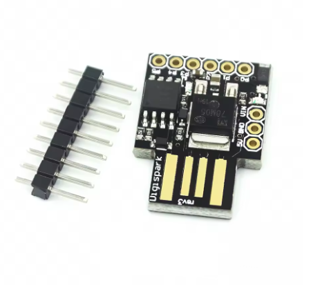
The ATtiny85 USB Development Board is a versatile, ultra-compact prototyping board built around the powerful yet minimal ATtiny85 8-bit AVR microcontroller. Designed as a smaller, more affordable alternative to traditional Arduino boards, this module is perfect for projects where space, simplicity, and efficiency are key.
This board simplifies the development process by integrating a direct USB interface, eliminating the need for bulky external programmers. It comes pre-flashed with a special bootloader (commonly Micronucleus or similar), allowing it to be programmed effortlessly using the familiar Arduino IDE environment. Simply plug it into any computer USB port, upload your code, and you are ready to go.
Despite its diminutive size, the ATtiny85 chip packs a punch with 8KB of Flash memory and access to multiple I/O pins that support Digital I/O, Pulse Width Modulation (PWM) for smooth LED fading or motor control, and Analog-to-Digital Conversion (ADC) for reading sensors. This robust functionality, combined with its breadboard-friendly design and integrated voltage regulation, makes it an ideal choice for creating small, embeddable gadgets, wearable electronics, sensor interfaces, and countless other custom DIY projects.
Direct USB Interface: Plugs directly into any standard USB-A port for both power and programming.
Arduino IDE Compatible: Easily programmable using the familiar and extensive Arduino ecosystem with the appropriate board definitions.
Integrated Bootloader: Pre-loaded with a USB bootloader (e.g., Micronucleus) for programming without an external ISP programmer.
Versatile GPIO Access: Provides access to 6 usable I/O pins supporting a variety of functions (Digital I/O, PWM, ADC, I2C, SPI).
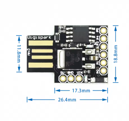
Compact & Breadboard-Friendly: Small form factor designed to slot directly into a breadboard without obstructing other pins.
Onboard LED: A built-in LED for basic debugging and status indication.
Voltage Regulation: Includes onboard 5V regulator and 3.3V power output pin for powering external components safely.
Usage
This module streamlines project development with its ability to plug directly into a computer’s USB port.
Programming Instructions
Prepare Arduino IDE: Install the necessary board definitions for the ATtiny microcontroller in your Arduino IDE preferences and Board Manager.
Configure Settings: Select “ATtiny25/45/85” and choose the settings matching the board’s internal clock (typically 8 MHz internal oscillator).
Upload Sketch: Click “Upload” in the IDE. When the IDE indicates that it’s “uploading,” plug the ATtiny85 board into your computer’s USB port. The bootloader is active for a brief window to accept the new firmware.
Application Scenarios
Miniature Gadgets: Building simple, functional USB-powered devices or small electronic novelties.
Custom Keyboards: Creating simple USB Human Interface Devices (HID) using libraries like DigiKeyboard.
Sensor Nodes: Implementing low-power data logging or simple data acquisition from sensors.
LED Controllers: Designing unique and complex lighting effects in a tiny footprint.
Embedded Systems Prototyping: Testing concepts quickly before moving to a final PCB design
Q: Do I need an external programmer to use this board?
No. The integrated USB interface and pre-flashed bootloader allow you to program the board directly from your computer’s USB port using the Arduino IDE
Q: How many pins can I use for my projects?
You have access to 6 general purpose I/O pins. Note that two of these pins are shared for the USB communication during the brief programming phase, but they become available for your sketch’s use once the program starts running.
Q: What is the recommended power source?
The simplest way is to plug it directly into a 5V USB port. If using an external power source via the VIN pin, a regulated 7V to 12V DC source is recommended. The board also offers a 3.3V output pin to power low-voltage peripherals.
Q: Is this board compatible with all Arduino libraries?
No. While it uses the Arduino IDE, the ATtiny85 has limited memory (512 bytes of SRAM) and a different architecture than the ATmega328P chip found in the Arduino Uno. Many complex libraries will be too large or incompatible. You must use libraries specifically optimized for the ATtiny series
Q: What is the maximum operating frequency?
The default internal clock speed when using the common Arduino bootloader configurations is 8 MHz