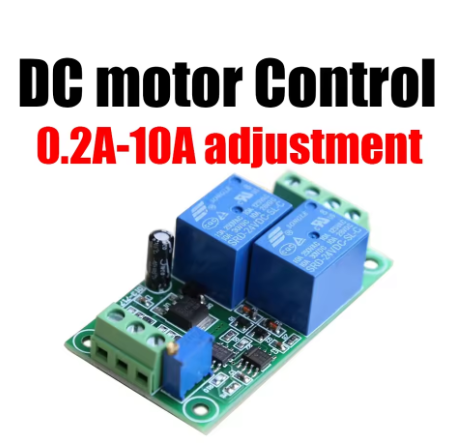
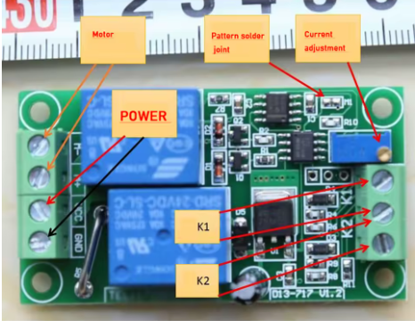
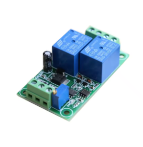
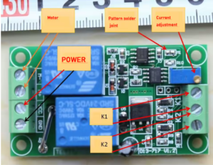
Dual-Channel LM393 Voltage Comparator Module – DC 24V 10A Max, Onboard IC for Precision Monitoring

SKU: FA2178-2
Comparator IC

LM393 (dual differential comparator)

Channels

2 independent comparison channels

Relay Output Rating

DC 24V at 10A maximum

Reference Adjustment

Onboard trimpot potentiometer per channel

Output Type

Open-collector (relay-driven)

Operating Voltage

DC 5V–24V (module dependent)

Indicator

LED per channel

Terminal Type

Screw terminals for power, input, and output

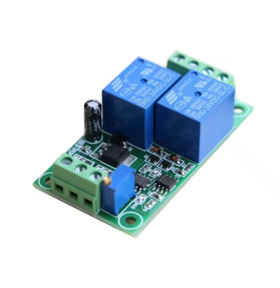
The Dual-Channel LM393 Voltage Comparator Module is a versatile signal detection and switching board designed for precision voltage monitoring and comparison applications. Built around the industry-standard LM393 dual differential comparator IC, this module provides two independent comparison channels that can detect when an input voltage rises above or falls below a user-adjustable reference level.

The LM393 is a widely used dual voltage comparator known for its precision, stability, and low power consumption. Each of the two channels operates independently, allowing you to monitor two separate signals simultaneously or set up a window comparator configuration for detecting when a voltage falls within or outside a specific range. The onboard trimpot potentiometers allow precise adjustment of the reference voltage for each channel, giving you fine control over the switching threshold.

The module’s outputs are open-collector type, which means they can be configured to pull low when the input exceeds the reference. This makes the board directly compatible with relays, LEDs, buzzers, and microcontroller inputs. The onboard relay (in this module variant) is rated for DC 24V at 10A maximum, providing a high-current switching output that can directly control motors, solenoids, lamps, and other loads without additional driver circuitry.

Typical applications include battery voltage monitoring, over-voltage and under-voltage protection, light-activated switching (with a photoresistor input), temperature threshold detection (with a thermistor), and industrial process control. The module operates from a wide input voltage range and provides clear LED indicators for each channel, showing the current output state at a glance.

The board is compact, fully assembled, and ready to use. Screw terminals provide secure connections for power, input signals, and relay outputs. Whether you are building a battery management system, a safety cut-off circuit, or an automated monitoring station, the Dual-Channel LM393 Voltage Comparator Module offers a reliable, adjustable solution.


Features

  • Dual independent comparison channels — Monitor two separate signals simultaneously.

  • LM393 precision comparator IC — Industry-standard chip for stable, accurate voltage comparison.

  • Adjustable reference voltage — Onboard trimpot potentiometers allow fine threshold tuning per channel.

  • Open-collector outputs — Directly compatible with relays, LEDs, buzzers, and MCU inputs.

  • High-current relay output — Rated DC 24V at 10A max for direct load switching.

  • LED status indicators — Clear visual feedback for each channel’s output state.

  • Wide operating voltage range — Flexible power supply options for various applications.

  • Screw terminal connections — Secure, tool-tightened wiring for power, signal, and load.


Technical Specifications

# Parameter Specification
1 Comparator IC LM393 (dual differential comparator)
2 Channels 2 independent comparison channels
3 Relay Output Rating DC 24V at 10A maximum
4 Reference Adjustment Onboard trimpot potentiometer per channel
5 Output Type Open-collector (relay-driven)
6 Operating Voltage DC 5V–24V (module dependent)
7 Indicator LED per channel
8 Terminal Type Screw terminals for power, input, and output

Usage

Getting Started

  1. Power the module — Connect a suitable DC supply (typically 5V–24V depending on the module variant) to the VCC and GND terminals.

  2. Connect the input signal — Wire the voltage signal you want to monitor to the input terminal of the desired channel.

  3. Adjust the reference voltage — Turn the trimpot potentiometer on the corresponding channel to set the threshold at which the output should switch. Use a multimeter to measure the reference voltage for precision.

  4. Connect the load — Wire the device you want to control (motor, lamp, relay coil, etc.) to the relay output terminals, observing the normally-open (NO) and normally-closed (NC) markings.

  5. Test the circuit — Vary the input voltage across the threshold. The relay should click and the LED should change state when the threshold is crossed.

Typical Applications

  • Battery voltage monitoring — Detect when a battery drops below a safe threshold and trigger an alarm or disconnect.

  • Over-voltage and under-voltage protection — Protect equipment from harmful voltage levels.

  • Light-activated switching — Use a photoresistor as the input to create a dark/light detector.

  • Temperature threshold detection — Use a thermistor to trigger a relay at a specific temperature.

  • Industrial process control — Monitor sensor signals and activate outputs when conditions are met.

  • Automated testing — Detect pass/fail conditions in production testing.

  • Educational projects — Teaching comparator circuits, threshold detection, and relay control.

Notes for Business Buyers

  • Dual-channel design — Reduces component count and board space for multi-signal monitoring.

  • High-current relay output — Directly drives loads without external driver circuitry.

  • Adjustable thresholds — Trimpot tuning provides flexibility across different applications.

  • Suitable for bulk purchasing — Ideal for industrial control, automation, and educational projects.

Q: What is the LM393 used for?

The LM393 is a dual voltage comparator. It compares two input voltages and outputs a signal indicating which is higher. It is commonly used for threshold detection, voltage monitoring, and signal conditioning.

Q: How do I adjust the threshold voltage?

Turn the trimpot potentiometer on the corresponding channel. Use a multimeter to measure the voltage at the reference pin while adjusting to achieve the desired threshold.

Q: What is the maximum load this module can switch?

The onboard relay is rated for DC 24V at 10A maximum. For inductive loads like motors, keep the load current below 60–70% of the rated value for reliable operation.

Q: Can I use this module with AC loads?

This module is designed for DC loads up to 24V. For AC load switching, a different relay module rated for AC voltage is required.

Q: What is the operating voltage of the module?

The module typically operates from DC 5V to 24V, depending on the specific variant. Check the product label or datasheet for your version.

Q: What type of output does the module provide?

The LM393 provides an open-collector output, which is used to drive the onboard relay. The relay provides isolated switching for external loads.

Q: Can I connect this module directly to a microcontroller?

Yes. The open-collector output can be connected to a microcontroller input, though the relay provides the main switching function. Ensure voltage levels are compatible.

Q: What is the difference between normally-open (NO) and normally-closed (NC)?

NO contacts are open by default and close when the relay is activated. NC contacts are closed by default and open when the relay is activated. Choose the configuration that matches your application’s fail-safe requirements.

Q: Does the module have LED indicators?

Yes. Each channel has an LED that indicates the current output state, making it easy to monitor the module’s operation at a glance.

Q: Can I purchase in bulk for a school or company?

Yes. This module is suitable for both individual users and business purchasing, including industrial control, automation projects, and educational kits.