Product Overview
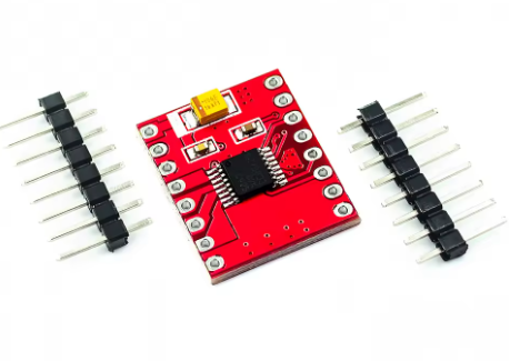
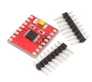
The DRV8833 Dual Motor Drive Module is a compact, high-efficiency motor driver designed for modern DIY electronics, robotics, and battery-powered applications. Based on the advanced Texas Instruments DRV8833 IC , this module represents a significant leap forward from traditional drivers, offering ultra-low MOSFET on-resistance of just 360 mΩ (combined high-side + low-side) . This results in minimal heat generation, eliminating the need for bulky heatsinks and making it ideal for space-constrained and power-sensitive projects .
This dual-channel H-bridge driver serves as the perfect interface between your microcontroller (Arduino, ESP32, STM32, Raspberry Pi Pico) and small to medium-sized DC motors or bipolar stepper motors. It can independently control the speed and direction of two DC motors or drive one bipolar stepper motor with precision .
With a wide operating voltage range of 2.7V to 10.8V and integrated current regulation, the DRV8833 is exceptionally well-suited for battery-operated devices like robotics, smart locks, portable cameras, and toys . Its simple PWM interface makes it easy to use, while comprehensive protection features ensure reliable operation even under fault conditions .
Key Features
-
Dual H-Bridge MOSFET Design: Integrates two NMOS H-bridges with ultra-low on-resistance (360 mΩ total) for high efficiency and minimal heat generation compared to bipolar transistor-based drivers .
-
High Output Current: Delivers 1.5A RMS continuous current per channel (2A peak) in standard packages. When paralleling both outputs for a single motor, it can achieve up to 3A RMS (4A peak) .
-
Wide Operating Voltage Range: Accepts motor supply voltage from 2.7V to 10.8V DC, making it compatible with 1-cell LiPo (3.7V), 2-cell LiPo (7.4V), and standard 5V or 9V systems .
-
Integrated Current Regulation: Features fixed-frequency PWM current regulation (current chopping) that limits motor current without requiring microcontroller intervention. The current limit is set by an external sense resistor (200mV reference) .
-
Low-Power Sleep Mode: Includes a dedicated nSLEEP pin that puts the device into an ultra-low power state (1.6 µA typical at 5V ), drastically extending battery life in portable applications .
-
Simple PWM Control Interface: Uses a standard 2-pin per motor interface (xIN1, xIN2) for direction and speed control, compatible with nearly all microcontrollers. Speed is controlled by PWM duty cycle; direction by logic levels .
-
Multiple Decay Modes: Supports both slow and fast decay modes for optimal current recirculation, selectable via the input pin states. This allows tuning for different motor characteristics and operating conditions .
-
Comprehensive Protection Features:
-
Overcurrent Protection (OCP): Shuts down the bridge if a fault persists, with automatic retry .
-
Thermal Shutdown (TSD): Disables outputs if the die temperature exceeds safe limits, with automatic recovery .
-
Undervoltage Lockout (UVLO): Prevents operation at unsafe low voltages .
-
Fault Indication Pin (nFAULT): Provides diagnostic feedback when a fault occurs .
-
Compact and Lightweight: Miniature footprint (as small as 3mm x 3mm for the QFN package on some modules ) allows for integration into the tightest spaces.
-
Versatile Motor Support: Capable of driving two brushed DC motors, one bipolar stepper motor, solenoids, or other inductive loads .
-
Direct Drop-In Replacement: Pin-compatible with TB6612 driver modules in many implementations, allowing easy upgrades .
Technical Specifications
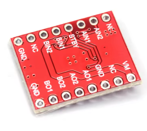
Pinout & Interface Guide
The DRV8833 module typically provides clear labeling for all essential pins.
Power Pins
-
VM (Motor Voltage): Main motor power supply input (2.7V-10.8V). Connect to your battery or power source .
-
VCC (Logic Voltage): Logic supply for the internal circuitry (2.7V-5.5V). Often connected to your microcontroller’s 5V or 3.3V output .
-
GND: Common ground. Must be connected to both power supply ground and microcontroller ground.
Motor Output Pins
-
AOUT1 / AOUT2: Outputs for Motor A (Channel 1). Connect your first DC motor here .
-
BOUT1 / BOUT2: Outputs for Motor B (Channel 2). Connect your second DC motor here .
-
For Stepper Motors: Connect one coil to AOUT1/AOUT2 and the other coil to BOUT1/BOUT2.
Control Pins
-
AIN1 / AIN2: Logic inputs for controlling Motor A direction and speed .
-
BIN1 / BIN2: Logic inputs for controlling Motor B direction and speed .
-
nSLEEP: Sleep mode control. Drive HIGH for normal operation, LOW to enter ultra-low power sleep mode . If not using sleep mode, connect to VCC (through a pull-up resistor if VM > 6.5V) .
-
nFAULT: Fault output (open-drain). Goes LOW when a fault (overcurrent, thermal shutdown, UVLO) occurs. Requires an external pull-up resistor to VCC if used .
Current Sense Pins
Usage Guide
Important Pre-Operation Requirements
-
Power Supply Voltage: Ensure your motor power supply (VM) is within 2.7V to 10.8V. Exceeding 10.8V can permanently damage the module .
-
Power Supply Current: Choose a power supply capable of delivering the required current for your motors. For two motors running at 1.5A each, a 3A+ supply is recommended.
-
Logic Voltage: Provide the appropriate logic voltage (VCC) to match your microcontroller (typically 5V or 3.3V) .
-
Grounding: Always connect the module’s GND to both the power supply ground and your microcontroller ground to ensure proper signal reference.
-
Capacitor Recommendation: It is good practice to place a 0.1µF ceramic capacitor and a larger electrolytic capacitor (e.g., 47µF-100µF) near the VM and GND pins to decouple the motor power supply and absorb voltage spikes .
Control Logic Table
The DRV8833 uses a simple 2-pin interface per motor. The following truth table applies to both channels :
PWM Speed Control
Speed is controlled by applying a PWM signal to one of the input pins while holding the other at a fixed logic level. The DRV8833 supports two decay modes for PWM operation :
Decay Mode Selection:
-
Fast Decay: Current recirculates through body diodes. Provides faster current drop, useful for high-speed switching.
-
Slow Decay: Current recirculates by shorting the motor winding. Provides smoother current and can be more efficient at lower speeds .
Setting Current Limit (Optional)
If your module includes current sense resistors (or pads to add them), you can set a precise current limit:
-
Connect a sense resistor between xISEN and GND.
-
The current limit is calculated as: I_limit = 200 mV / R_sense .
-
Example: With a 0.2Ω resistor, the limit is 200mV / 0.2Ω = 1A.
-
If current limiting is not needed, simply connect xISEN directly to GND .
Basic Arduino Example Code
This example controls one DC motor (Channel A) with forward, reverse, brake, and coast functions.
#define AIN1 5
#define AIN2 6
#define SLEEP 7
void setup() {
pinMode(AIN1, OUTPUT);
pinMode(AIN2, OUTPUT);
pinMode(SLEEP, OUTPUT);
digitalWrite(SLEEP, HIGH);
digitalWrite(AIN1, LOW);
digitalWrite(AIN2, LOW);
}
void loop() {
analogWrite(AIN1, 191);
digitalWrite(AIN2, LOW);
delay(3000);
digitalWrite(AIN1, LOW);
digitalWrite(AIN2, LOW);
delay(1000);
digitalWrite(AIN1, LOW);
analogWrite(AIN2, 127);
delay(3000);
digitalWrite(AIN1, HIGH);
digitalWrite(AIN2, HIGH);
delay(1000);
digitalWrite(SLEEP, LOW);
delay(2000);
digitalWrite(SLEEP, HIGH);
delay(500);
}
Q: What is the difference between the DRV8833 and older drivers like the L298N?
The DRV8833 uses modern MOSFET technology with very low on-resistance (360 mΩ), making it far more efficient and cooler-running than the L298N, which uses bipolar transistors with significant voltage drop . The DRV8833 is also much smaller, operates at lower voltages (2.7-10.8V), and includes integrated current regulation and sleep mode
Q: What types of motors can I use with the DRV8833?
It can drive:
-
Two brushed DC motors (independently controlled)
-
One bipolar stepper motor (4-wire)
-
Solenoids and other inductive loads
Q: Can I use this with a 3.3V microcontroller like an ESP32 or Raspberry Pi Pico?
Yes. The logic inputs (xIN1, xIN2, nSLEEP) are compatible with 3.3V logic levels when VCC is set to 3.3V. Ensure your module’s VCC pin is connected to your microcontroller’s 3.3V output
Q: What is the maximum current I can get from this driver?
The standard per-channel continuous current is 1.5A RMS (2A peak). If you parallel both channels to drive a single motor, you can achieve up to 3A RMS (4A peak) . Actual current also depends on PCB design, cooling, and ambient temperature.
Q: What is the sleep mode and why would I use it?
Sleep mode is an ultra-low power state (1.6 µA) that disables the motor drivers and most internal circuitry . It’s ideal for battery-powered projects where the motors are not needed for extended periods (e.g., between movements in a smart lock or robot), dramatically extending battery life.
Q: How do I control motor speed?
Speed is controlled by applying a PWM (Pulse Width Modulation) signal to one of the input pins while holding the other at a fixed logic level. The duty cycle of the PWM signal determines the average voltage to the motor, thus controlling its speed
Q: What is the difference between brake and coast?
-
Coast (00): Both motor outputs are high-impedance (disconnected). The motor free-runs to a stop due to friction and inertia .
-
Brake (11): Both motor outputs are shorted to ground. This creates a braking effect that stops the motor much more rapidly
Q: How do I set the current limit?
The DRV8833 uses an external sense resistor on the xISEN pins. The current limit is calculated as I_limit = 200mV / R_sense . If your module has these resistors pre-soldered, the current limit is fixed. If not, you can add resistors or simply connect xISEN to GND to disable current limiting
Q: Do I need to use the nSLEEP pin?
If you don’t need sleep mode, you should pull the nSLEEP pin HIGH to keep the driver active. This can be done by connecting it directly to VCC (through a 10kΩ-75kΩ resistor if VM is above 6.5V to limit current to the internal Zener clamp) . Many modules have this pin pulled high by default.
Q: What power supply should I use?
Choose a supply that meets these criteria:
-
Voltage: Between 2.7V and 10.8V DC. Match the voltage to your motor’s rating for optimal performance.
-
Current: The supply should be capable of delivering at least the total expected motor current plus a 20-30% margin. For example, for two 1A motors, use a 2.5A or 3A supply.
-
Type: A regulated DC power supply or a suitable battery pack (LiPo, NiMH, Alkaline).
Q: The motor runs weakly or loses torque. What's wrong?
Common causes and solutions:
-
Low voltage: If using a battery, it may be discharged. Measure VM under load.
-
Power supply inadequate: The supply may be current-limiting or voltage-sagging under load.
-
Current limiting active: If you have set a current limit via xISEN, the motor may be hitting that limit. Check the limit value.
-
PWM frequency: If the frequency is too high, motor inductance may prevent full current from building. Try a lower frequency (e.g., 1kHz-20kHz)
Q: The chip gets warm. Is this normal?
At 1.5A continuous current, some warmth is normal. The DRV8833’s low on-resistance (360 mΩ) means power dissipation is approximately I² × R = (1.5²) × 0.36 = 0.81 watts per channel. This will cause noticeable warmth but should not become scorching hot. If it gets too hot to touch, check for short circuits or excessive current
Q: The chip suddenly stops working. Did it burn out?
Possibly, but first check:
-
Thermal shutdown: The chip may have overheated and shut down. Allow it to cool; it will automatically resume .
-
Overcurrent protection: A momentary short may have triggered OCP. The driver will retry automatically .
-
Power supply: Check if VM is still within range and stable.
Q: The motor doesn't move at all. What should I check?
Follow this checklist:
-
Power OK? Check VM voltage at the module pins (2.7V-10.8V).
-
Logic OK? Check VCC voltage (2.7V-5.5V) .
-
Sleep mode? Ensure nSLEEP is HIGH (or connected to VCC) .
-
Enable/Inputs? Verify with a multimeter that your microcontroller is sending the correct signals to AIN1/AIN2.
-
Connections? Check all motor and power connections are secure.
-
Fault? If using nFAULT, check if it’s pulled LOW, indicating a fault condition.
Q: The motor only runs in one direction.
This usually indicates:
-
One of the input pins (xIN1 or xIN2) is not being driven correctly. Check your code and wiring.
-
A MOSFET in one half of the H-bridge may be damaged, often due to a short circuit or overcurrent event .
-
Verify that both input pins can be toggled HIGH and LOW by measuring them directly.
Q: The motor vibrates or runs roughly.
Possible causes:
-
PWM frequency too low: Audible noise and vibration can occur at low frequencies. Try increasing the PWM frequency above the audible range (e.g., 20kHz) .
-
Decay mode mismatch: Try switching between slow and fast decay modes to see which works better with your motor .
-
Power supply noise: Add decoupling capacitors near the module.
Q: The nFAULT pin is low. What does this mean?
A low nFAULT indicates one of the protection circuits has been triggered :
-
Overcurrent (OCP): A short circuit or excessive current on one of the bridges.
-
Thermal Shutdown (TSD): The chip has overheated.
-
Undervoltage (UVLO): VM has dropped below the safe operating threshold.
Turn off power, check for shorts, and allow the chip to cool if necessary. The fault will clear automatically when the condition is resolved
Q: Can I connect two motors in parallel to a single channel for more current?
Not recommended. Each channel is designed to drive one inductive load (a motor). Paralleling motors can cause unpredictable current sharing and may overload the channel. If you need more current for a single motor, use the parallel mode (connecting both channels to one motor) as described in the datasheet
Q: How do I use the parallel mode for a single high-current motor?
To parallel the channels:
-
Connect AOUT1 and BOUT1 together to one motor terminal.
-
Connect AOUT2 and BOUT2 together to the other motor terminal.
-
Drive both bridges with the same signals (connect AIN1 and BIN1 together, and AIN2 and BIN2 together).
This effectively doubles the current capability to 3A RMS