Description
Product Overview
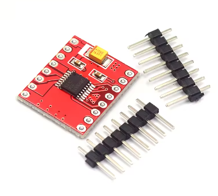
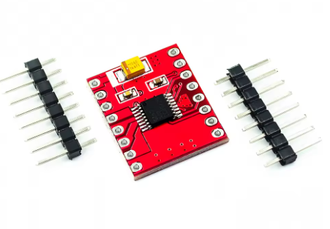
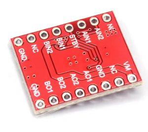
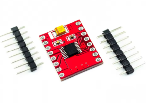
The DRV8833 Dual Motor Drive Module is a compact, high-efficiency motor driver designed for modern DIY electronics, robotics, and battery-powered applications. Based on the advanced Texas Instruments DRV8833 IC , this module represents a significant leap forward from traditional drivers, offering ultra-low MOSFET on-resistance of just 360 mΩ (combined high-side + low-side) . This results in minimal heat generation, eliminating the need for bulky heatsinks and making it ideal for space-constrained and power-sensitive projects .
This dual-channel H-bridge driver serves as the perfect interface between your microcontroller (Arduino, ESP32, STM32, Raspberry Pi Pico) and small to medium-sized DC motors or bipolar stepper motors. It can independently control the speed and direction of two DC motors or drive one bipolar stepper motor with precision .
With a wide operating voltage range of 2.7V to 10.8V and integrated current regulation, the DRV8833 is exceptionally well-suited for battery-operated devices like robotics, smart locks, portable cameras, and toys . Its simple PWM interface makes it easy to use, while comprehensive protection features ensure reliable operation even under fault conditions .
Key Features
-
Dual H-Bridge MOSFET Design: Integrates two NMOS H-bridges with ultra-low on-resistance (360 mΩ total) for high efficiency and minimal heat generation compared to bipolar transistor-based drivers .
-
High Output Current: Delivers 1.5A RMS continuous current per channel (2A peak) in standard packages. When paralleling both outputs for a single motor, it can achieve up to 3A RMS (4A peak) .
-
Wide Operating Voltage Range: Accepts motor supply voltage from 2.7V to 10.8V DC, making it compatible with 1-cell LiPo (3.7V), 2-cell LiPo (7.4V), and standard 5V or 9V systems .
-
Integrated Current Regulation: Features fixed-frequency PWM current regulation (current chopping) that limits motor current without requiring microcontroller intervention. The current limit is set by an external sense resistor (200mV reference) .
-
Low-Power Sleep Mode: Includes a dedicated nSLEEP pin that puts the device into an ultra-low power state (1.6 µA typical at 5V ), drastically extending battery life in portable applications .
-
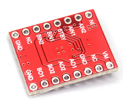
Simple PWM Control Interface: Uses a standard 2-pin per motor interface (xIN1, xIN2) for direction and speed control, compatible with nearly all microcontrollers. Speed is controlled by PWM duty cycle; direction by logic levels .
-
Multiple Decay Modes: Supports both slow and fast decay modes for optimal current recirculation, selectable via the input pin states. This allows tuning for different motor characteristics and operating conditions .
-
Comprehensive Protection Features:
-
Overcurrent Protection (OCP): Shuts down the bridge if a fault persists, with automatic retry .
-
Thermal Shutdown (TSD): Disables outputs if the die temperature exceeds safe limits, with automatic recovery .
-
Undervoltage Lockout (UVLO): Prevents operation at unsafe low voltages .
-
Fault Indication Pin (nFAULT): Provides diagnostic feedback when a fault occurs .
-
-
Compact and Lightweight: Miniature footprint (as small as 3mm x 3mm for the QFN package on some modules ) allows for integration into the tightest spaces.
-
Versatile Motor Support: Capable of driving two brushed DC motors, one bipolar stepper motor, solenoids, or other inductive loads .
-
Direct Drop-In Replacement: Pin-compatible with TB6612 driver modules in many implementations, allowing easy upgrades .
Technical Specifications
| Parameter | Operating Value |
|---|---|
| Motor Supply Voltage (VM) | 2.7V – 10.8V DC |
| Logic Supply Voltage (VCC) | 2.7V – 5.5V (typically from microcontroller) |
| Output Current (Continuous, Per Channel) | 1.5A RMS |
| Output Current (Peak, Per Channel) | 2A |
| Output Current (Parallel Mode, Continuous) | 3A RMS |
| Output Current (Parallel Mode, Peak) | 4A |
| MOSFET On-Resistance (HS + LS) | 360 mΩ (typical) |
| Sleep Mode Current | 1.6 µA (typical at 5V) |
| Current Sense Reference Voltage | 200 mV (fixed) |
| PWM Frequency Range | Up to 20 kHz (typical) |
| Operating Temperature Range | -40°C to +85°C (ambient) |
| Protection Features | OCP, TSD, UVLO, nFAULT indication |
| Board Dimensions | Varies by module (typically 15-25mm x 20-30mm) |
Reviews
There are no reviews yet.