GY-271 HMC5883L 3 Axis Module Magnetic Field Sensor

SKU: FA2166
Sensor Chip

Honeywell HMC5883L

Operating Voltage

3V – 5V DC

Active Current

100 µA (typical) / 8 mA – 10 mA (max)

Measurement Range

±1.3 to ±8 Gauss (selectable)

Resolution

Up to 5 mG (at 3V supply)

Heading Accuracy

±1° to ±2°

Maximum Output Rate

160 Hz

Communication Protocol

I2C (Standard up to 400 kHz)

Default I2C Address

0x1E (7-bit) / 0x3C (8-bit write)

Operating Temperature

-40°C to +85°C

Module Dimensions

Approx. 15mm × 13mm × 3.5mm

Weight

Approx. 4g

Product Overview

The GY-271 HMC5883L 3-Axis Magnetic Sensor Module is a compact, high-precision electronic compass designed for low-field magnetic sensing. It enables you to determine spatial orientation by measuring the Earth’s magnetic field along the X, Y, and Z axes, providing accurate heading information for navigation and motion-sensing projects .

At its core is the Honeywell HMC5883L chip – a surface-mount multi-chip module that integrates magneto-resistive sensors with a 12-bit ADC, amplification, automatic degaussing straps, and offset cancellation . This combination allows the sensor to detect magnetic fields down to 5 milligauss and provide compass heading accuracy of approximately 1 to 2 degrees .

The module communicates via the simple I2C interface, requiring only two data lines (SDA and SCL) to connect to your microcontroller. With a wide operating voltage range of 3V to 5V, it is directly compatible with both 3.3V systems (ESP32, ESP8266, Raspberry Pi) and 5V systems (Arduino) .

Whether you are building a drone navigation system, a robot that needs to know which way is north, a weather station, or a handheld compass, the GY-271 module offers a reliable, low-cost, and easy-to-integrate solution.

Key Features

  • 3-Axis Magnetic Field Sensing: Measures magnetic field strength on X, Y, and Z axes simultaneously for full 3D orientation detection .

  • HMC5883L Chipset: Combines high-resolution magneto-resistive sensors with a 12-bit ADC for precise measurements .

  • I2C Digital Interface: Simple 2-wire communication (SDA, SCL) uses only two pins, saving valuable I/O resources .

  • Wide Voltage Compatibility: Operates on 3V – 5V DC, compatible with both 3.3V (ESP32, Raspberry Pi) and 5V (Arduino) systems .

  • Low Power Consumption: Consumes only 100 µA in active measurement mode, ideal for battery-powered applications .

  • Adjustable Measurement Range: User-selectable full-scale range from ±1.3 to ±8 Gauss .

  • High Output Data Rate: Maximum output rate of 160 Hz, suitable for real-time orientation tracking .

  • Data Ready Interrupt (DRDY): Optional pin indicates when new measurement data is available, simplifying efficient code design .

  • Compact Form Factor: Small PCB size (approx. 15mm × 13mm) fits easily into space-constrained projects .

Technical Specifications

Parameter Operating Value
Sensor Chip Honeywell HMC5883L
Operating Voltage 3V – 5V DC
Active Current 100 µA (typical) / 8 mA – 10 mA (max) 
Measurement Range ±1.3 to ±8 Gauss (selectable) 
Resolution Up to 5 mG (at 3V supply) 
Heading Accuracy ±1° to ±2° 
Maximum Output Rate 160 Hz 
Communication Protocol I2C (Standard up to 400 kHz) 
Default I2C Address 0x1E (7-bit) / 0x3C (8-bit write) 
Operating Temperature -40°C to +85°C
Module Dimensions Approx. 15mm × 13mm × 3.5mm 
Weight Approx. 4g 

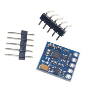
Pinout & Connection Guide

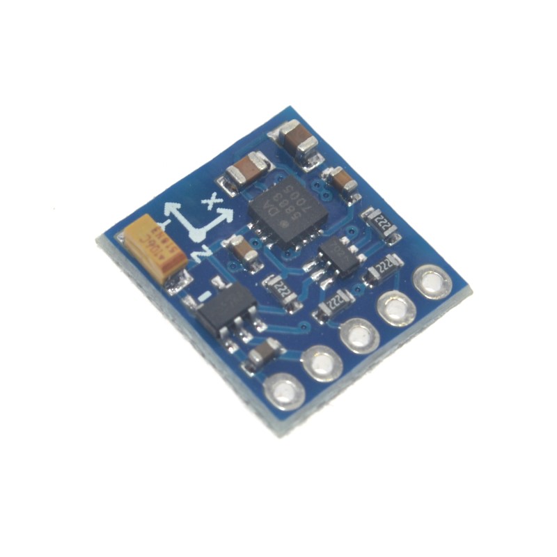
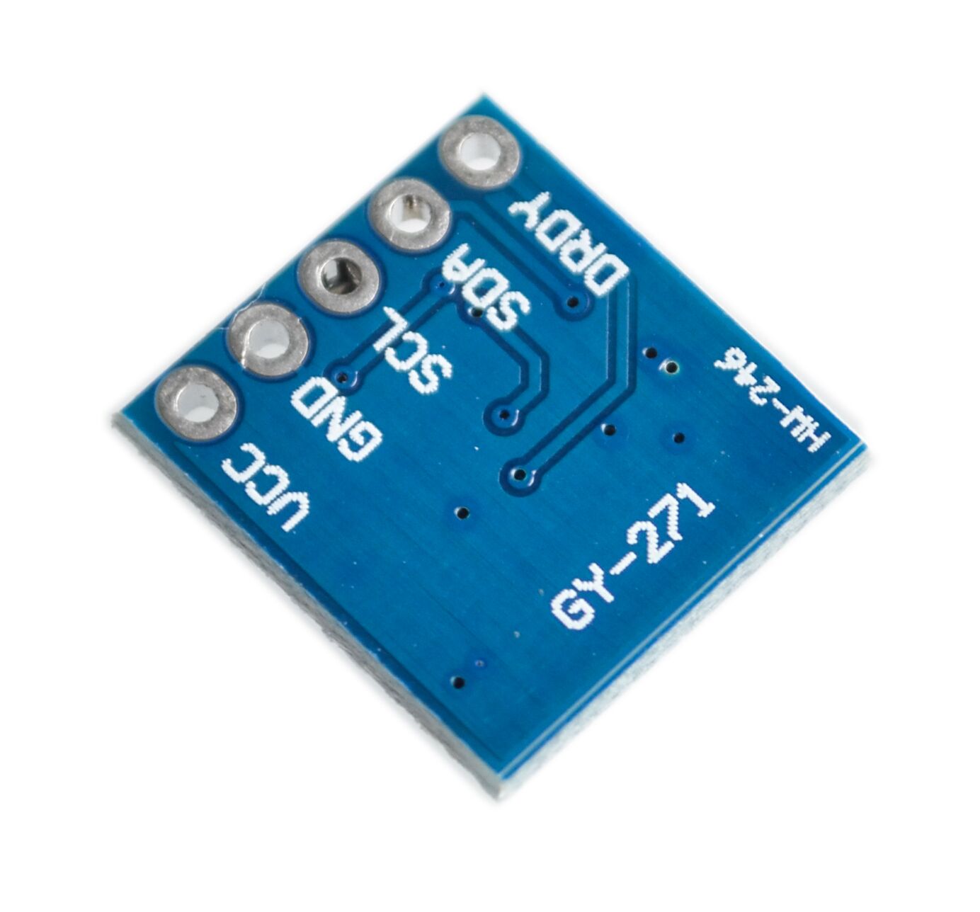
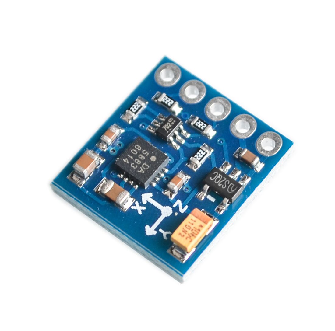
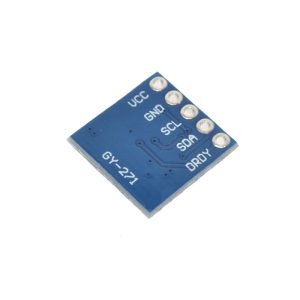
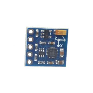
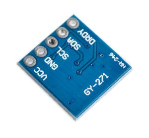
The GY-271 module features a 5-pin configuration, clearly labeled on the PCB.

Pin Definitions

Pin Label Function Description
1 VCC Power Supply Connect to 3.3V or 5V DC power source
2 GND Ground Common ground connection
3 SCL I2C Clock Line Connect to SCL pin of your microcontroller
4 SDA I2C Data Line Connect to SDA pin of your microcontroller
5 DRDY Data Ready Interrupt Optional output; pulses LOW for 250µs when new data is ready 

Wiring Diagrams

For Arduino Uno / Nano:

GY-271 Pin Arduino Pin
VCC 5V
GND GND
SCL A5 (SCL)
SDA A4 (SDA)

For ESP32:

GY-271 Pin ESP32 Pin
VCC 3.3V
GND GND
SCL GPIO22 (SCL)
SDA GPIO21 (SDA)

For ESP8266 (NodeMCU):

GY-271 Pin ESP8266 Pin
VCC 3.3V
GND GND
SCL GPIO5 (D1)
SDA GPIO4 (D2)

Theory of Operation

How a Magnetometer Works

The HMC5883L uses Anisotropic Magneto-Resistive (AMR) sensors – material that changes its electrical resistance in response to an external magnetic field. A bridge circuit measures these resistance changes, and the on-chip 12-bit ADC converts them to digital values . By measuring the magnetic field in three orthogonal axes (X, Y, Z), the Earth’s magnetic field vector can be determined, and the direction to magnetic north can be calculated.

Calculating Heading (Azimuth)

For a sensor held horizontally (parallel to the ground), the heading (azimuth) in degrees is calculated as:

text
heading = atan2(Y, X) × (180 / π)

Where:

  • X = magnetometer reading from the X-axis (after calibration)

  • Y = magnetometer reading from the Y-axis (after calibration)

If heading is negative, add 360° to get a result in the 0°–360° range.

Important: This formula gives magnetic north. To obtain true north, you must apply the magnetic declination (variation) for your geographic location, which can be found online or calculated.

When the Sensor is Not Horizontal

If your sensor is mounted vertically or at an angle, you must incorporate accelerometer data to perform tilt compensation using pitch and roll angles before calculating the heading.

Raw Data Interpretation

The 12-bit ADC outputs values ranging from -2048 to 2047. The measured magnetic field in Gauss is calculated as: field = raw_value × (gain / 2048), where gain is the selected sensitivity (e.g., 1090 LSB/Gauss for the ±1.3G range).

Usage Guide

Software Setup (Arduino IDE)

Step 1: Install Required Libraries

The easiest way to use the HMC5883L is with the Adafruit_HMC5883_Unified library .

  1. Open Arduino IDE → Sketch → Include Library → Manage Libraries

  2. Search for “Adafruit HMC5883”

  3. Install the library by Adafruit (this will also install the Adafruit Sensor and BusIO libraries)

Step 2: Basic Test Sketch

cpp
/*
  GY-271 HMC5883L Compass Basic Read Example
*/

#include <Wire.h>
#include <Adafruit_Sensor.h>
#include <Adafruit_HMC5883_U.h>

Adafruit_HMC5883_Unified mag = Adafruit_HMC5883_Unified(12345);

void setup() {
  Serial.begin(9600);
  
  if (!mag.begin()) {
    Serial.println("HMC5883L sensor not found! Check wiring.");
    while (1);
  }
  
  // Set measurement range
  // Options: HMC5883L_RANGE_1_3GA, HMC5883L_RANGE_1_9GA,
  //          HMC5883L_RANGE_2_5GA, HMC5883L_RANGE_4_0GA,
  //          HMC5883L_RANGE_4_7GA, HMC5883L_RANGE_5_6GA,
  //          HMC5883L_RANGE_8_1GA
  mag.setRange(HMC5883L_RANGE_1_3GA);
  
  // Set measurement mode (single, continuous, etc.)
  mag.setMeasurementMode(HMC5883L_CONTINUOUS);
  
  // Set data rate (0.75, 1.5, 3, 7.5, 15, 30, 75, 220 Hz)
  mag.setDataRate(HMC5883L_DATARATE_15_HZ);
  
  Serial.println("GY-271 HMC5883L Ready");
  Serial.println("-----------------------------");
}

void loop() {
  sensors_event_t event;
  mag.getEvent(&event);
  
  // Magnetic field readings in microteslas (µT)
  // Convert to Gauss by dividing by 100 (1 Gauss = 100 µT)
  float x = event.magnetic.x / 100.0;
  float y = event.magnetic.y / 100.0;
  float z = event.magnetic.z / 100.0;
  
  // Calculate heading in degrees (0° = North)
  float heading = atan2(y, x) * 180 / PI;
  if (heading < 0) heading += 360;
  
  Serial.print("X: "); Serial.print(x);
  Serial.print(" G, Y: "); Serial.print(y);
  Serial.print(" G, Z: "); Serial.print(z);
  Serial.print(" G  |  Heading: ");
  Serial.println(heading);
  
  delay(100);
}

Step 3: Manual I2C Implementation (No Library)

If you prefer not to use the Adafruit library, you can control the HMC5883L directly using the Wire library.

cpp
/*
  GY-271 Manual I2C Read Example
*/

#include <Wire.h>

#define HMC5883L_ADDR 0x1E
#define CONFIG_A_REG  0x00
#define CONFIG_B_REG  0x01
#define MODE_REG      0x02
#define DATA_REG_BEGIN 0x03

void setup() {
  Serial.begin(9600);
  Wire.begin();
  
  // Initialize HMC5883L
  Wire.beginTransmission(HMC5883L_ADDR);
  Wire.write(CONFIG_A_REG);
  Wire.write(0x70);  // 8 samples averaged, 15 Hz output rate
  Wire.endTransmission();
  
  Wire.beginTransmission(HMC5883L_ADDR);
  Wire.write(CONFIG_B_REG);
  Wire.write(0xA0);  // ±1.3 Gauss range, gain 1090 LSB/Gauss
  Wire.endTransmission();
  
  Wire.beginTransmission(HMC5883L_ADDR);
  Wire.write(MODE_REG);
  Wire.write(0x00);  // Continuous measurement mode
  Wire.endTransmission();
  
  Serial.println("GY-271 Manual Mode Ready");
}

void loop() {
  // Request 6 bytes of data (X, Y, Z as 16-bit each)
  Wire.beginTransmission(HMC5883L_ADDR);
  Wire.write(DATA_REG_BEGIN);
  Wire.endTransmission();
  Wire.requestFrom(HMC5883L_ADDR, 6);
  
  if (Wire.available() >= 6) {
    int16_t x = Wire.read() << 8 | Wire.read();
    int16_t z = Wire.read() << 8 | Wire.read();  // Note: Z is third
    int16_t y = Wire.read() << 8 | Wire.read();  // Y is fourth
    // (The register order is X, Z, Y)
    
    // Convert to Gauss (using ±1.3G range: 1090 LSB/G)
    float fx = x / 1090.0;
    float fy = y / 1090.0;
    float fz = z / 1090.0;
    
    float heading = atan2(fy, fx) * 180 / PI;
    if (heading < 0) heading += 360;
    
    Serial.print("Heading: ");
    Serial.println(heading);
  }
  
  delay(100);
}

Calibration for Accurate Heading

The magnetometer measures the Earth’s magnetic field, but nearby electronics (motors, wires, batteries) introduce hard-iron and soft-iron distortions. Calibration is essential for accurate heading.

Simple Hard-Iron Offset Calibration

  1. Place the sensor in a fixed location.

  2. Rotate the sensor 360° in the horizontal plane.

  3. Record the minimum and maximum raw values for X and Y axes.

  4. Calculate offsets:

    text
    X_offset = (X_max + X_min) / 2
    Y_offset = (Y_max + Y_min) / 2
  5. Apply offsets to all future readings:

    text
    X_cal = X_raw - X_offset
    Y_cal = Y_raw - Y_offset
  6. Recalculate heading using calibrated values.

Calibration Code Example

cpp
/*
  HMC5883L Hard-Iron Calibration Sketch
  Rotate sensor 360° and record min/max values
*/

#include <Wire.h>
#include <Adafruit_HMC5883_U.h>

Adafruit_HMC5883_Unified mag = Adafruit_HMC5883_Unified(12345);

int16_t xMin = 32767, xMax = -32768, yMin = 32767, yMax = -32768;

void setup() {
  Serial.begin(9600);
  mag.begin();
  mag.setRange(HMC5883L_RANGE_1_3GA);
  mag.setMeasurementMode(HMC5883L_CONTINUOUS);
  
  Serial.println("Rotate the sensor 360° in horizontal plane...");
  delay(3000);
}

void loop() {
  sensors_event_t event;
  mag.getEvent(&event);
  
  int16_t x = event.magnetic.x;
  int16_t y = event.magnetic.y;
  
  if (x < xMin) xMin = x;
  if (x > xMax) xMax = x;
  if (y < yMin) yMin = y;
  if (y > yMax) yMax = y;
  
  Serial.print("X: "); Serial.print(x);
  Serial.print("  | Y: "); Serial.print(y);
  Serial.print("  | Xmin: "); Serial.print(xMin);
  Serial.print("  | Xmax: "); Serial.print(xMax);
  Serial.print("  | Ymin: "); Serial.print(yMin);
  Serial.print("  | Ymax: "); Serial.println(yMax);
  
  delay(100);
}

Once offsets are determined, apply them in your main code:

cpp
float x = (event.magnetic.x - xOffset) / 1090.0;
float y = (event.magnetic.y - yOffset) / 1090.0;
float heading = atan2(y, x) * 180 / PI;

Using the DRDY Pin (Optional)

The DRDY pin pulses LOW for 250µs when new measurement data is ready . This can be used to trigger an interrupt in your microcontroller, allowing you to read data only when new values are available rather than continuously polling.

cpp
// Configure external interrupt on DRDY pin
attachInterrupt(digitalPinToInterrupt(DRDY_PIN), dataReadyISR, FALLING);

Selecting the Measurement Range

The measurement range trades off between sensitivity and maximum field detection:

Register Setting Gain (LSB/G) Range Best For
0x20 1370 ±0.88 G Weak magnetic fields (Earth’s field ~0.5G)
0x40 1090 ±1.3 G Recommended default for compassing
0x60 820 ±1.9 G Stronger fields
0x80 660 ±2.5 G Noisy environments
0xA0 440 ±4.0 G Very strong fields
0xC0 390 ±4.7 G Industrial environments
0xE0 295 ±8.1 G Maximum range

For most compass applications, the ±1.3 Gauss range (1090 LSB/G) provides the best sensitivity .

Q: What is the default I2C address of the GY-271 module?

The default 7-bit I2C address is 0x1E (8-bit write address 0x3C, read address 0x3D) . This address is fixed, so only one HMC5883L can be used per I2C bus .

Q: Why is my compass not showing the correct heading?

The most common cause is lack of calibration. Nearby electronics (motors, wires, batteries) create magnetic interference that must be compensated for using hard-iron and soft-iron calibration. Rotate the sensor 360° to collect min/max values and apply the offsets described above. Also, ensure you are not near large metal objects or strong magnetic sources.

Q: Can I use the GY-271 with a 5V Arduino directly?

Yes. The module operates on 3V–5V and includes onboard circuitry that makes it compatible with both 3.3V and 5V systems. Connect VCC to 5V and SDA/SCL directly to the I2C pins .

Q: Why am I not reading any data from the sensor?

Common issues:

  1. I2C wiring: Verify VCC, GND, SCL, and SDA connections.

  2. Pull-up resistors: The I2C bus requires pull-ups (typically 4.7kΩ). Most modules include them, but if you experience issues, add external pull-ups .

  3. Sensor initialization: Ensure you are setting the configuration registers correctly.

  4. Address: Verify the device address using an I2C scanner sketch.

  5. Power: Ensure your power supply can deliver adequate current.

Q: How do I convert the raw output values to Gauss?

Divide the raw ADC value by the gain (sensitivity) for your selected range. For the ±1.3 Gauss range, the gain is 1090 LSB/Gauss, so: Gauss = raw_value / 1090. For other ranges, refer to the gain table above .

Q: What is the DRDY pin used for?

The DRDY (Data Ready) pin pulses LOW for 250 microseconds when new measurement data is available . This can be connected to a microcontroller interrupt pin to trigger data reading only when new data is ready, rather than continuously polling. This is optional – if not used, simply leave the pin disconnected.

Q: Can I use this module with an ESP32 or ESP8266?

Yes. Connect VCC to 3.3V and SDA/SCL to the appropriate I2C pins (GPIO21/22 for ESP32, GPIO4/5 for ESP8266). The Adafruit library works on these platforms .

Q: Does the GY-271 measure magnetic north or true north?

The HMC5883L measures magnetic north. To obtain true north, you must apply the magnetic declination (variation) for your geographic location, which can be found online or calculated using a GPS.

Q: What is the difference between the HMC5883L and the QMC5883L?

The QMC5883L is a compatible alternative to the HMC5883L, with a different I2C address (0x0D). Some GY-271 modules may ship with the QMC5883L instead . If your compass is not responding at address 0x1E, try the QMC5883LCompass library and address 0x0D.

Q: How accurate is the heading measurement?

After proper calibration, the HMC5883L can achieve heading accuracy of ±1° to ±2° . For best results, calibrate the sensor in the final installation environment and maintain it in a horizontal position (or implement tilt compensation using accelerometer data).