Product Overview
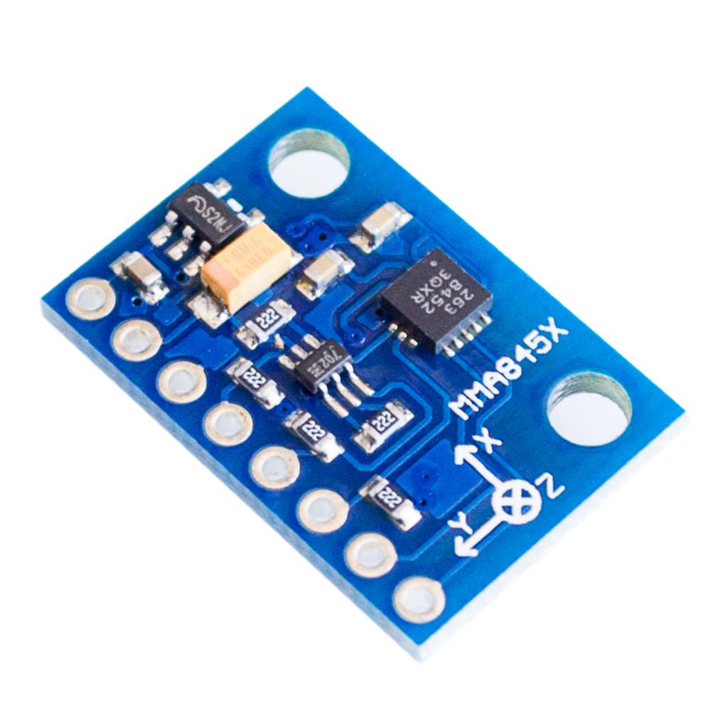
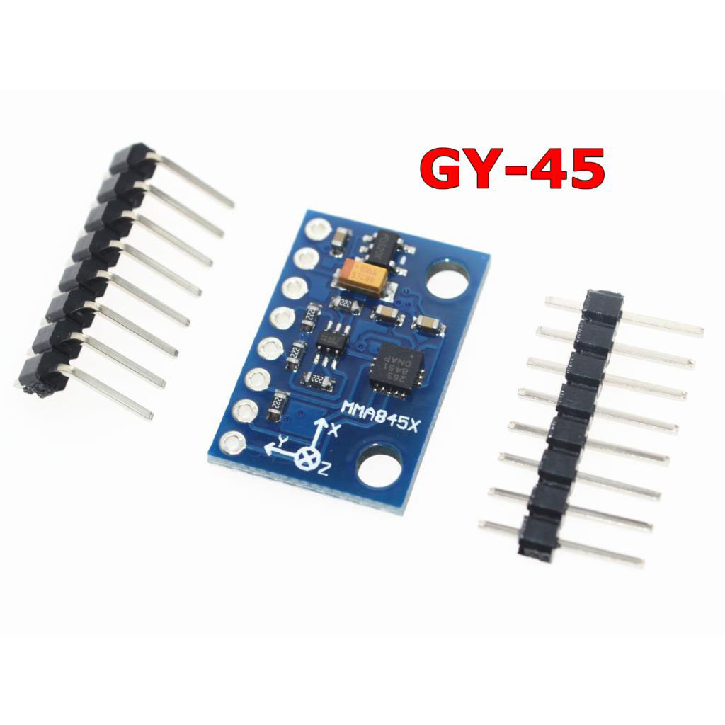
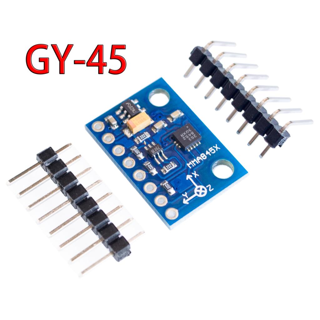
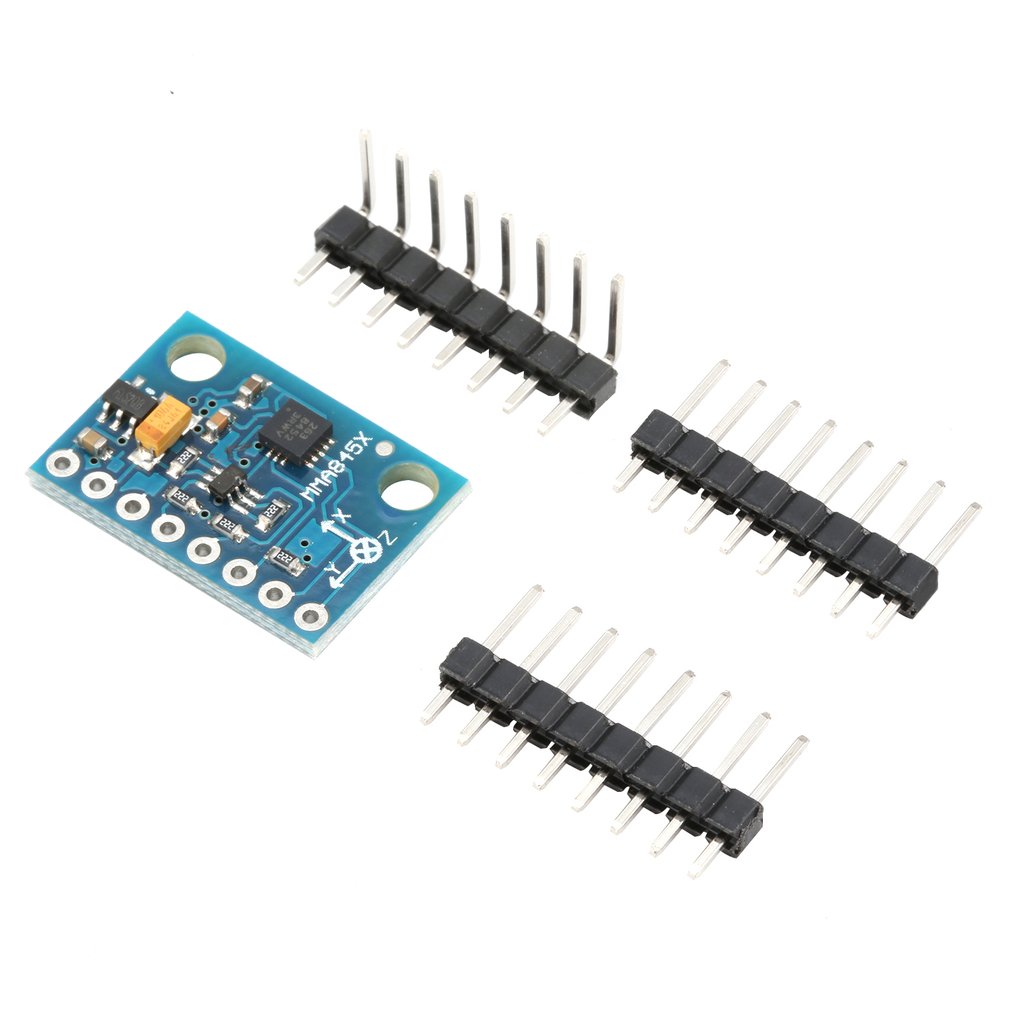
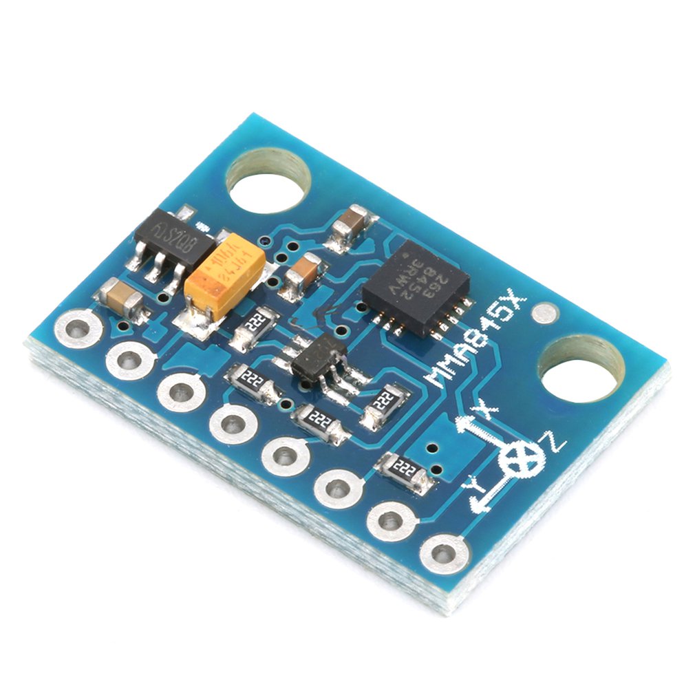
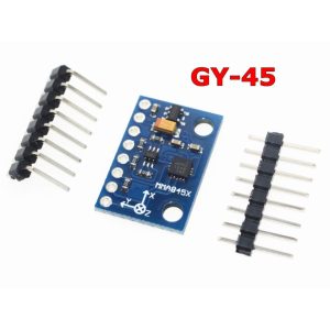
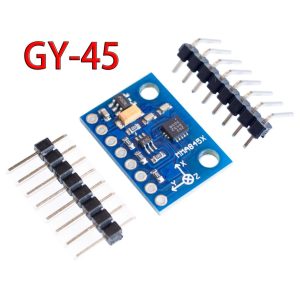
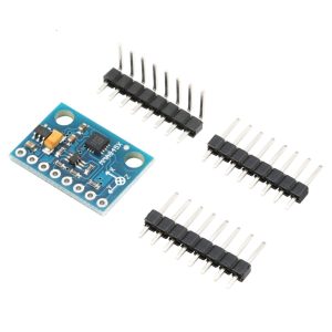
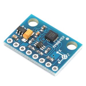
The GY-45 MMA8452 3-Axis Accelerometer Module is a high-precision, low-power digital motion sensor based on the NXP MMA8452Q integrated circuit. This sensor is used to measure acceleration, tilt, vibration, and motion detection along the X, Y, and Z axes. It is widely used in robotics, IoT devices, wearable electronics, and gesture recognition applications.
The MMA8452Q is a smart, low-power, three-axis, capacitive micromachined accelerometer with 12 bits of resolution. It includes embedded functions with flexible user-programmable options, allowing configuration of up to two interrupt pins, which reduces the load on the host processor by eliminating the need for continuous polling.
The GY-45 module is designed for easy integration with 3V to 5V systems, making it compatible with both Arduino (5V) and ESP32/ESP8266 (3.3V) without additional level shifting. With selectable ±2g/±4g/±8g measurement ranges and output data rates from 1.56 Hz to 800 Hz, this sensor is suitable for a wide range of applications, from static tilt measurement to high-frequency vibration monitoring.
Key Features
-
High-Precision 12-bit Digital Output: Provides 12-bit resolution for accurate acceleration measurement, configurable to 8-bit for faster readings
-
Selectable Measurement Ranges: User-selectable full-scale ranges of ±2g, ±4g, and ±8g for flexible sensitivity adjustment
-
Low Power Consumption: Operating current ranges from 6 µA to 165 µA, making it ideal for battery-powered applications
-
I2C Digital Interface: Simple 2-wire communication (SDA, SCL) with configurable I2C address (0x1C or 0x1D), allowing multiple sensors on the same bus
-
Embedded Motion Detection Features:
-
Freefall or motion detection
-
Pulse (tap/double-tap) detection
-
Transient (jolt) detection
-
Orientation Detection: Portrait/landscape detection with programmable hysteresis for stable switching
-
Automatic ODR Adjustment: Auto-wake and return-to-sleep functionality automatically changes output data rate to save power
-
High-Pass Filtered Data: Real-time output of high-pass filtered data removes DC offset for accurate dynamic motion measurement
-
Wide Voltage Compatibility: Operates on 3V to 5V DC power supply; I/O voltage range from 1.6V to 3.6V
Technical Specifications
Pinout & Connection Guide
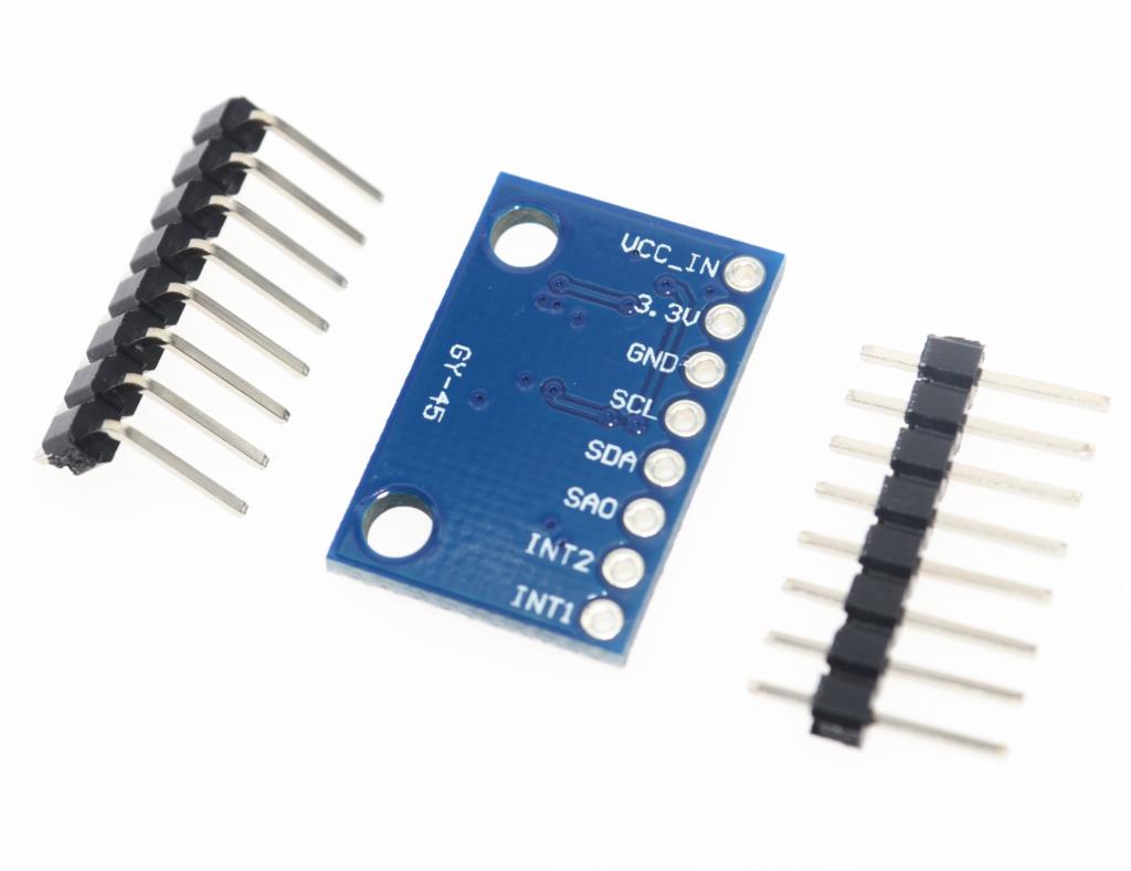
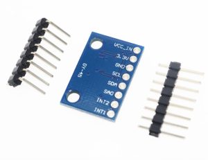
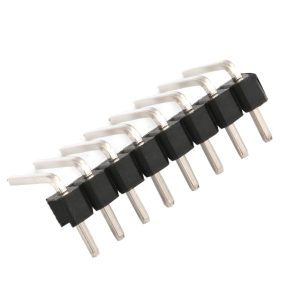
The GY-45 MMA8452 module features a compact 5-pin or 6-pin configuration for easy wiring.
Pin Definitions
I2C Pin Mapping for Common Development Boards
Wiring Diagram (Arduino Uno)
GY-45 Module          →    Arduino Uno
─────────────────────────────────────────
VCC                   →    5V
GND                   →    GND
SCL                   →    A5 (SCL)
SDA                   →    A4 (SDA)
SA0                   →    GND (for address 0x1C)
INT1 (optional)       →    D2 (or any digital pin)
Usage Guide
Software Setup (Arduino IDE)
Step 1: Install Required Libraries
The MMA8452 is supported by several libraries:
Option A: “MMA8452” Library – Simple and easy to use
-
Open Arduino IDE → Sketch → Include Library → Manage Libraries
-
Search for “MMA8452”
-
Install the library by Adafruit or other trusted developer
Option B: “SparkFun MMA8452Q” Library – Comprehensive features
Step 2: Basic Test Sketch
GY-45 MMA8452 Accelerometer Basic Read Example
*/
#include <Wire.h>
#include <Adafruit_MMA8452.h>
Adafruit_MMA8452 mma = Adafruit_MMA8452();
void setup() {
Serial.begin(9600);
if (!mma.begin()) {
Serial.println("Could not find MMA8452 sensor. Check wiring!");
while (1);
}
Serial.println("GY-45 MMA8452 Sensor Ready");
mma.setRange(MMA8452_RANGE_2_G);
Serial.print("Range set to: ");
Serial.print(2 << mma.getRange());
Serial.println("g");
}
void loop() {
mma.read();
Serial.print("X: ");
Serial.print(mma.x);
Serial.print(" Y: ");
Serial.print(mma.y);
Serial.print(" Z: ");
Serial.print(mma.z);
Serial.println();
float xg = mma.x / 4096.0;
float yg = mma.y / 4096.0;
float zg = mma.z / 4096.0;
Serial.print("Force (g): ");
Serial.print(xg);
Serial.print(", ");
Serial.print(yg);
Serial.print(", ");
Serial.println(zg);
float pitch = atan2(-xg, sqrt(yg * yg + zg * zg)) * 180 / PI;
float roll = atan2(yg, zg) * 180 / PI;
Serial.print("Pitch: ");
Serial.print(pitch);
Serial.print("°, Roll: ");
Serial.println(roll);
Serial.println();
delay(500);
}
Understanding the Data Output
The MMA8452Q outputs 12-bit data (range: -2048 to 2047). The sensitivity depends on the selected range:
Example: For ±2g range, an X-axis reading of 512 means 0.5g of acceleration.
Typical Orientation Readings (Stationary)
Configuring Motion Detection
MMA8452 Motion Detection Example
*/
#include <Wire.h>
#include <Adafruit_MMA8452.h>
Adafruit_MMA8452 mma = Adafruit_MMA8452();
void setup() {
Serial.begin(9600);
if (!mma.begin()) {
Serial.println("Sensor not found");
while (1);
}
mma.writeRegister(MMA8452_FF_MT_CFG, 0x38);
mma.writeRegister(MMA8452_FF_MT_THS, 0x0A);
mma.writeRegister(MMA8452_FF_MT_COUNT, 0x05);
mma.writeRegister(MMA8452_CTRL_REG4, 0x04);
mma.writeRegister(MMA8452_CTRL_REG5, 0x01);
}
void loop() {
if (mma.readTap() & 0x04) {
Serial.println("Freefall detected!");
}
delay(100);
}
Power Management for Battery-Powered Projects
Q: What is the resolution of the MMA8452 sensor?
The MMA8452Q provides 12-bit digital output (default). It can also be configured for 8-bit output for faster readings. The resolution allows detection of tilt changes as small as approximately 0.06°.
Q: Is the GY-45 MMA8452 compatible with 3.3V microcontrollers?
Yes. The module operates on 3V to 5V power and includes onboard regulation, making it directly compatible with both 3.3V (ESP32, ESP8266) and 5V (Arduino) systems.
Q: What is the difference between MMA8452 and MPU6050?
The MMA8452 is a 3-axis accelerometer only. The MPU6050 combines both 3-axis accelerometer and 3-axis gyroscope. Choose MMA8452 for applications requiring only tilt and motion detection (low power, simpler). Choose MPU6050 for full 6-DOF motion tracking.
Q: Can this sensor detect tap/double-tap gestures?
Yes. The MMA8452Q includes embedded pulse detection functionality that can detect single and double taps. This is configured through the device’s interrupt registers without requiring continuous processor polling.
Q: How do I select between ±2g, ±4g, and ±8g ranges?
Use the setRange() function in your library or write directly to the XYZ_DATA_CFG register. Example: mma.setRange(MMA8452_RANGE_2_G) for ±2g sensitivity.
Q: What are the two I2C addresses, and how do I select them?
The I2C address is determined by the SA0 pin:
Q: Why are my readings 0 or 4095?
This indicates communication failure or an incorrectly configured I2C address. Check your wiring and verify the correct I2C address using an I2C scanner sketch.
Q: Can the MMA8452 be used as a pedometer or step counter?
Yes. The MMA8452 is suitable for real-time activity analysis applications, including pedometer step counting. The embedded transient detection can be configured to detect step patterns.
Q: What is the purpose of the two interrupt pins (INT1, INT2)?
The two programmable interrupt pins can be configured to trigger on various events including freefall, motion, pulse detection, orientation change, and data ready. This offloads processing from the main microcontroller.
Q: How does the auto-wake/sleep function work?
The device automatically changes the output data rate (ODR) between a higher rate when motion is detected and a lower rate during inactivity. This significantly reduces power consumption while maintaining responsiveness.