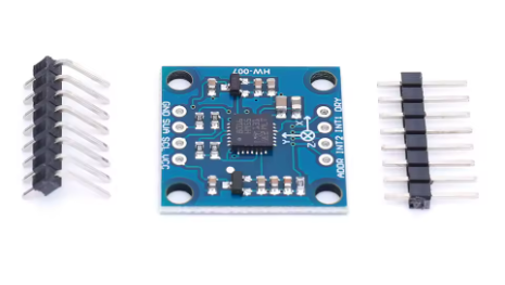
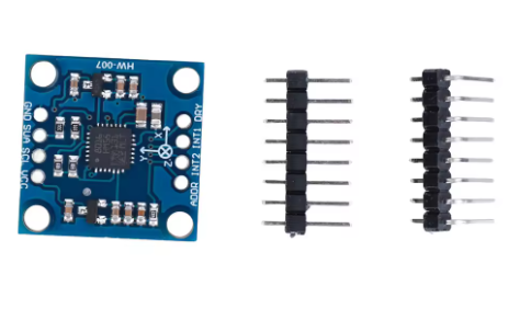
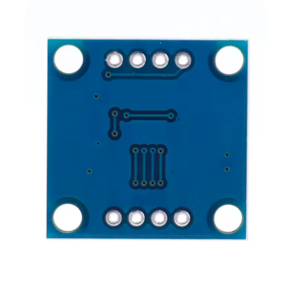
Product Overview
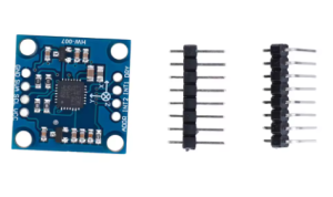
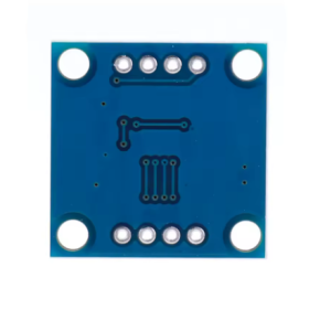
The GY-51 LSM303DLH Module is a powerful 6‑degree‑of‑freedom (6DOF) sensor that integrates a 3‑axis accelerometer and a 3‑axis magnetometer (electronic compass) in a single compact unit. Based on the STMicroelectronics LSM303DLH chip, this module provides a complete motion and orientation tracking solution for a wide range of applications, from robotics and navigation to portable devices and gaming.
Unlike separate accelerometer and compass modules, the LSM303DLH combines both sensing elements on a single chip, communicating with your microcontroller via the simple I²C protocol. This saves valuable GPIO pins and simplifies your hardware design while providing 16‑bit data output for high‑resolution readings . The chip includes programmable interrupt generators for free‑fall and motion detection, as well as 6‑dimensional orientation detection that can trigger when the device is moved up/down along any axis .
One of the key advantages of having both sensors on the same chip is the ability to perform tilt‑compensated compassing. By using the accelerometer data to correct for the device’s tilt, you can obtain accurate magnetic heading even when the sensor is not perfectly level. This is essential for reliable navigation in drones, robots, and handheld devices .
The GY-51 module is designed for easy integration, operating from 3V to 5V power and supporting both 3.3V and 5V logic levels. This makes it compatible with a wide range of microcontrollers, including Arduino, ESP32, ESP8266, Raspberry Pi, and STM32. Its compact size (approximately 23mm × 23mm) and low power consumption make it suitable for battery‑powered and portable projects .
Key Features
-
6‑DOF Integrated Sensor: Combines a 3‑axis accelerometer and a 3‑axis magnetometer in a single chip for complete motion and orientation tracking .
-
Selectable Acceleration Ranges: User‑selectable full‑scale ranges of ±2g, ±4g, and ±8g for flexible sensitivity adjustment .
-
Selectable Magnetic Field Ranges: Magnetic field full‑scale range selectable from ±1.3 to ±8.1 Gauss with seven intermediate steps, allowing optimization for different magnetic environments .
-
16‑bit Data Output: High‑resolution 16‑bit data output for both accelerometer and magnetometer channels, providing excellent detail and accuracy .
-
I²C Digital Interface: Simple 2‑wire communication (SDA, SCL) with support for both standard (100 kHz) and fast (400 kHz) modes .
-
Tilt‑Compensated Compass Capability: The accelerometer can be used to correct magnetometer readings for device tilt, enabling accurate heading even when the sensor is not horizontal .
-
Low Power Consumption: The accelerometer can operate in low‑power mode, making the module suitable for battery‑powered and portable devices .
-
Programmable Interrupt Features: Two independent interrupt generators can be configured for free‑fall detection, motion detection, and 6D orientation recognition (up/down events on any axis) .
-
Wide Compatibility: Operates on 3V‑5V power, directly compatible with both 3.3V and 5V microcontrollers like Arduino, ESP32, ESP8266, Raspberry Pi, and STM32 .
-
Embedded Self‑Test: Built‑in self‑test capability allows verification of sensor functionality in the final application .
-
Compact Module Size: Approximately 23mm × 23mm, ideal for space‑constrained and portable projects .
Technical Specifications
Pinout & Connection Guide
Pin Definitions
Note: Pin labels may vary slightly between GY‑51 board versions. Always verify the silkscreen on your specific module.
I²C Address Configuration
The I²C address is determined by the SA0 pin connection :
Note: The LSM303DLH uses different sub‑addresses for the accelerometer and magnetometer internally. High‑level libraries handle these differences automatically .
I²C Pin Mapping for Common Development Boards
Wiring Diagram (Arduino Uno)
GY-51 Module          →    Arduino Uno
─────────────────────────────────────────
VCC                   →    5V
GND                   →    GND
SCL                   →    A5 (SCL)
SDA                   →    A4 (SDA)
ADDR                  →    GND (default address)
INT1 (optional)       →    D2 (any digital pin)
Wiring Diagram (ESP32)
GY-51 Module          →    ESP32
─────────────────────────────────────────
VCC                   →    3.3V
GND                   →    GND
SCL                   →    GPIO22 (SCL)
SDA                   →    GPIO21 (SDA)
ADDR                  →    GND (default address)
Usage Guide
The Importance of Tilt‑Compensated Compasses
A raw magnetometer measures the Earth’s magnetic field, which is useful for determining heading. However, if the device is tilted (not horizontal), the magnetic field readings are affected, leading to heading errors. The GY‑51 solves this by also providing accelerometer data, allowing you to calculate the device’s tilt angles (pitch and roll). These angles can then be used to mathematically rotate the magnetometer readings into a horizontal plane, producing an accurate magnetic heading even when the sensor is not level . This is called a tilt‑compensated electronic compass.
Software Setup (Arduino IDE)
Step 1: Install Required Libraries
Several libraries support the LSM303DLH. The most commonly used is the “Pololu LSM303” library, which is well‑tested and provides high‑level functions for accessing accelerometer, magnetometer, and tilt‑compensated heading data.
-
Open Arduino IDE → Sketch → Include Library → Manage Libraries
-
Search for “Pololu LSM303”
-
Install the library by Pololu
Alternative library: “Adafruit LSM303” (also available via Library Manager).
Step 2: Basic Accelerometer & Magnetometer Read Example
This sketch initializes the sensor and reads raw accelerometer and magnetometer data.
GY-51 LSM303DLH Basic Read Example
Reads accelerometer and magnetometer data using the Pololu library
*/
#include <Wire.h>
#include <LSM303.h>
LSM303 compass;
void setup() {
Serial.begin(9600);
Wire.begin();
if (!compass.init()) {
Serial.println("Failed to initialize LSM303 sensor. Check wiring!");
while (1);
}
compass.enableDefault();
Serial.println("GY-51 LSM303DLH Sensor Ready");
}
void loop() {
compass.read();
Serial.print("Accel (mg): ");
Serial.print(compass.a.x);
Serial.print(", ");
Serial.print(compass.a.y);
Serial.print(", ");
Serial.println(compass.a.z);
Serial.print("Mag (uT): ");
Serial.print(compass.m.x);
Serial.print(", ");
Serial.print(compass.m.y);
Serial.print(", ");
Serial.println(compass.m.z);
Serial.println();
delay(500);
}
Step 3: Tilt‑Compensated Heading (Compass) Example
The real power of the LSM303DLH is the ability to generate a tilt‑compensated compass heading. This sketch calculates the heading in degrees.
GY-51 LSM303DLH Tilt-Compensated Compass Example
*/
#include <Wire.h>
#include <LSM303.h>
LSM303 compass;
void setup() {
Serial.begin(9600);
Wire.begin();
if (!compass.init()) {
Serial.println("Failed to initialize LSM303 sensor!");
while (1);
}
compass.enableDefault();
Serial.println("Tilt-Compensated Compass Ready");
Serial.println("Keep the sensor level for best results");
}
void loop() {
compass.read();
float heading = compass.heading();
Serial.print("Heading: ");
Serial.print(heading);
Serial.println(" degrees");
delay(200);
}
Step 4: Display Orientation Detection (6D Position)
The LSM303DLH can also detect the orientation of the device (which way is up). This is useful for screen rotation in mobile devices and for various gesture‑controlled applications.
GY-51 LSM303DLH 6D Orientation Detection
Detects which direction is up based on accelerometer data
*/
#include <Wire.h>
#include <LSM303.h>
LSM303 compass;
void setup() {
Serial.begin(9600);
Wire.begin();
compass.init();
compass.enableDefault();
Serial.println("6D Orientation Detection Ready");
}
void loop() {
compass.read();
if (compass.a.z > 800) {
Serial.println("Face Up");
} else if (compass.a.z < -800) {
Serial.println("Face Down");
} else if (compass.a.x > 800) {
Serial.println("Tilted Right (X down)");
} else if (compass.a.x < -800) {
Serial.println("Tilted Left (X up)");
} else if (compass.a.y > 800) {
Serial.println("Tilted Forward (Y down)");
} else if (compass.a.y < -800) {
Serial.println("Tilted Backward (Y up)");
} else {
Serial.println("Flat / Intermediate");
}
delay(500);
}
Calibration for Accurate Compassing
For accurate heading measurements, the magnetometer must be calibrated to compensate for hard‑iron offsets caused by nearby magnetic materials (batteries, wires, metallic components) on your device. The Pololu library includes a calibration example (LSM303_calibrate). The basic process involves:
-
Rotating the sensor in a figure‑eight pattern or around all axes.
-
The calibration sketch records the min and max readings for each axis.
-
These offset values are then stored and applied to future magnetometer readings.
// Example: Applying calibration offsets
compass.m_min.x = -500;
compass.m_min.y = -450;
compass.m_min.z = -600;
compass.m_max.x = +520;
compass.m_max.y = +480;
compass.m_max.z = +580;
Q: What is the difference between the GY-51 and other 6‑DOF sensors like the MPU6050?
The GY‑51 (LSM303DLH) combines a 3‑axis accelerometer and a 3‑axis magnetometer. This allows it to function as a tilt‑compensated electronic compass. The MPU‑6050 combines an accelerometer and a gyroscope, which is better for measuring angular velocity but cannot provide an absolute heading reference . The GY‑51 is the better choice for navigation and orientation sensing.
Q: Can the GY-51 be used to make a digital compass?
Yes, absolutely. The integrated 3‑axis magnetometer can measure the Earth’s magnetic field. By combining this with the 3‑axis accelerometer data to compensate for tilt, you can build a highly accurate electronic compass that works even when the device is not held horizontally .
Q: Is this sensor compatible with 5V logic systems like Arduino Uno?
Yes. The GY‑51 module operates on 3V–5V power and includes necessary components to interface directly with both 3.3V and 5V logic levels. You can connect it directly to an Arduino Uno’s 5V power and I²C pins without needing level shifters .
Q: What is the I²C address of the LSM303DLH?
The I²C address can be configured by the SA0 pin. When SA0 is connected to GND, the address is 0x19 (8‑bit: 0x32). When connected to VCC, the address is 0x19 (8‑bit: 0x33). Note that the accelerometer and magnetometer have different sub‑addresses, but high‑level libraries handle this automatically .
Q: How does the “6D orientation detection” work?
The “6D” feature monitors acceleration on all three axes. It can trigger an interrupt when the device is moved up (or down) along any of the X, Y, or Z axes. This is useful for detecting screen orientation changes (portrait/landscape) or motion activation .
Q: Can I use this sensor with a Raspberry Pi?
Yes. The module uses I²C for communication, which is fully supported on the Raspberry Pi. Connect VCC to 3.3V, GND to GND, SCL to GPIO3 (Pin 5), and SDA to GPIO2 (Pin 3). Enable I2C via raspi-config and use Python libraries like adafruit-circuitpython-lsm303 for easy data access.
Q: Do I need to calibrate the magnetometer for accurate heading?
For best results, yes. The magnetometer is sensitive to magnetic fields from your circuit (e.g., current in wires, nearby motors, batteries). This creates “hard‑iron” offsets that skew the readings. Running a calibration routine (moving the sensor in a figure‑eight pattern) will measure these offsets and allow you to correct the heading data .
Q: What does “tilt‑compensated” mean?
A raw compass only works accurately when held flat. “Tilt‑compensated” means the device uses accelerometer data to mathematically correct the magnetometer readings, accounting for the tilt angle (pitch and roll). This allows you to get an accurate heading even when the sensor is at an angle .
Q: What are the main applications for this sensor?
The LSM303DLH is suitable for a wide range of applications, including: electronic compasses for navigation, robotics heading reference, position detection, motion‑activated functions, free‑fall detection (for hard drive protection), screen orientation for handheld devices, gaming controllers, virtual reality input devices, and vibration monitoring .
Q: How do I handle the interrupt pins (INT1, INT2)?
The INT1 and INT2 pins are optional outputs. They can be programmed to go HIGH when specific events occur, such as free‑fall detection, motion above a threshold, or orientation change. You can connect them to digital input pins on your microcontroller to trigger interrupt service routines, offloading processing from your main loop .
Q: Why do I get “Failed to initialize” errors?
This error typically indicates a wiring or power issue. Check that VCC and GND are properly connected and that your power source can supply enough current. Also, verify the I²C connections (SDA to SDA, SCL to SCL) and check for any address conflicts if you have other I²C devices on the same bus .
Q: Where can I find example code for this module?
The Pololu LSM303 and Adafruit LSM303 libraries (available through the Arduino Library Manager) are excellent starting points. They include examples for reading raw data, tilt‑compensated heading calculation, and calibration. The STMicroelectronics datasheet for the LSM303DLH also provides detailed register maps and programming information .