Product Overview
The GY-9250 9-Axis Motion Sensor Module is a high-performance motion tracking board based on the InvenSense MPU-9250 sensor. This module integrates a 3-axis gyroscope, a 3-axis accelerometer, and a Digital Motion Processor (DMP) for complex motion processing .
Important Note: This is a refurbished unit. The magnetometer function is not operational on this module. You will only have access to 6-axis motion data (gyroscope + accelerometer), not the full 9-axis functionality .
The module communicates via I2C or SPI interfaces, giving you flexibility in connecting to your microcontroller. It is equipped with an onboard 3.3V voltage regulator and logic level converters, allowing direct connection to both 3.3V and 5V systems like Arduino, ESP32, ESP8266, Raspberry Pi, and STM32 .
The MPU-9250 is a multi-chip module (MCM) that contains two dies in a single QFN package: a 3-axis gyroscope, a 3-axis accelerometer, and a 3-axis magnetometer – though the magnetometer on this specific unit is non-functional. The DMP (Digital Motion Processor) can offload motion processing tasks from your main microcontroller, enabling complex orientation tracking with minimal CPU load .
Whether you are building a drone flight controller, a self-balancing robot, a VR headset, or any application requiring motion sensing, this refurbished GY-9250 module offers a cost-effective solution for 6-axis motion tracking.
Key Features
-
9-Axis Sensor (Magnetometer Non-Functional): Based on MPU-9250 with 3-axis gyroscope, 3-axis accelerometer, and Digital Motion Processor (DMP). The magnetometer is not operational on this refurbished unit .
-
Digital Motion Processor (DMP): Onboard processor can perform complex motion processing (sensor fusion) independently, reducing load on your main microcontroller .
-
Dual Communication Interfaces: Supports both I2C (up to 400 kHz) and SPI (up to 1 MHz) protocols for flexible microcontroller integration .
-
Onboard 3.3V Regulator & Level Shifter: Accepts 3V–5V power input and includes logic level conversion, making it directly compatible with both 3.3V and 5V systems .
-
16‑bit ADC Output: Built-in 16-bit analog-to-digital converters provide high-resolution data output for gyroscope and accelerometer .
-
Selectable Measurement Ranges: Gyroscope: ±250, ±500, ±1000, ±2000 dps; Accelerometer: ±2g, ±4g, ±8g, ±16g .
-
Built-in Filters: Onboard filters reduce noise from motors and other high-current electronics, ensuring cleaner readings .
-
Onboard Pull-up/Down Resistors: Includes pull-up resistors on SDA, SCL, and nCS lines, and pull-down resistors on FSYNC and AD0 for simplified wiring .
-
Power Indicator LED: Visual confirmation when the module is powered .
-
Immersion Gold PCB: High-quality PCB with gold-plated pads for better solderability and corrosion resistance .
Technical Specifications
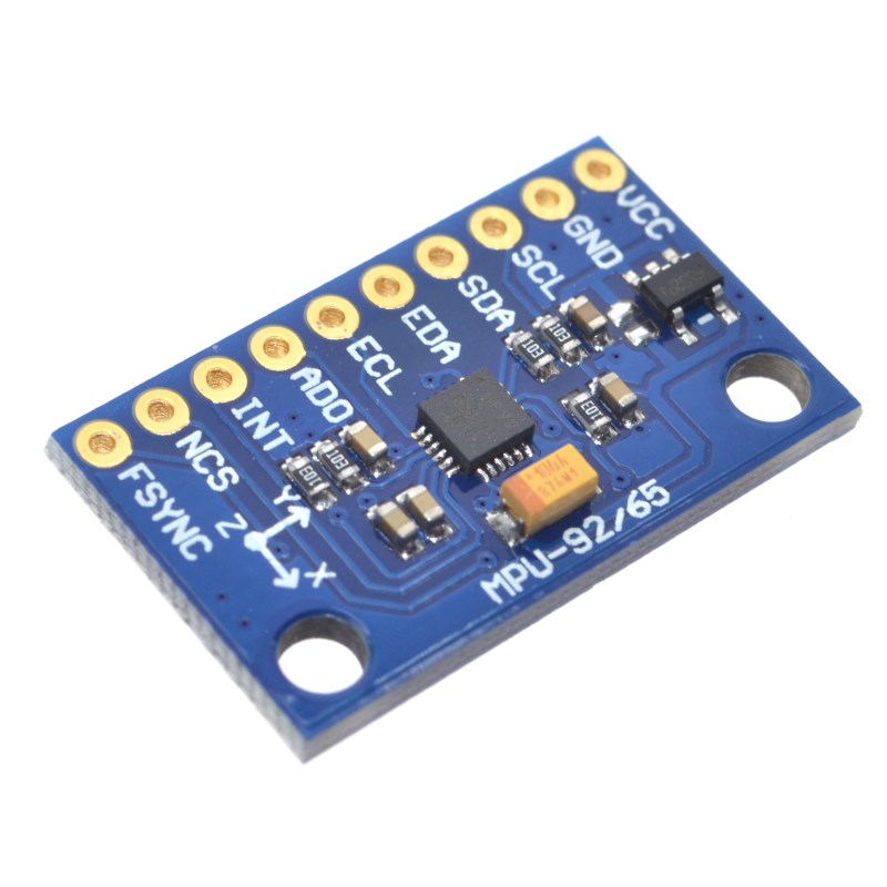
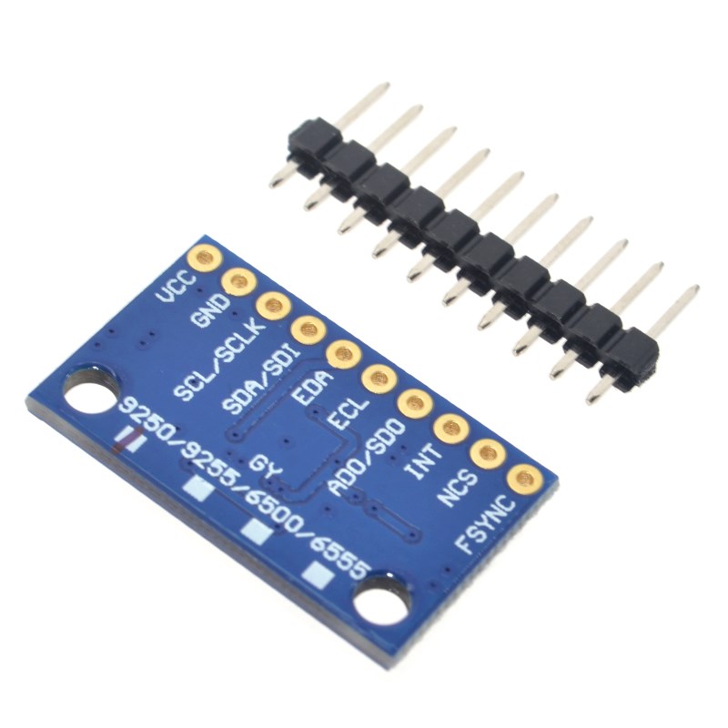
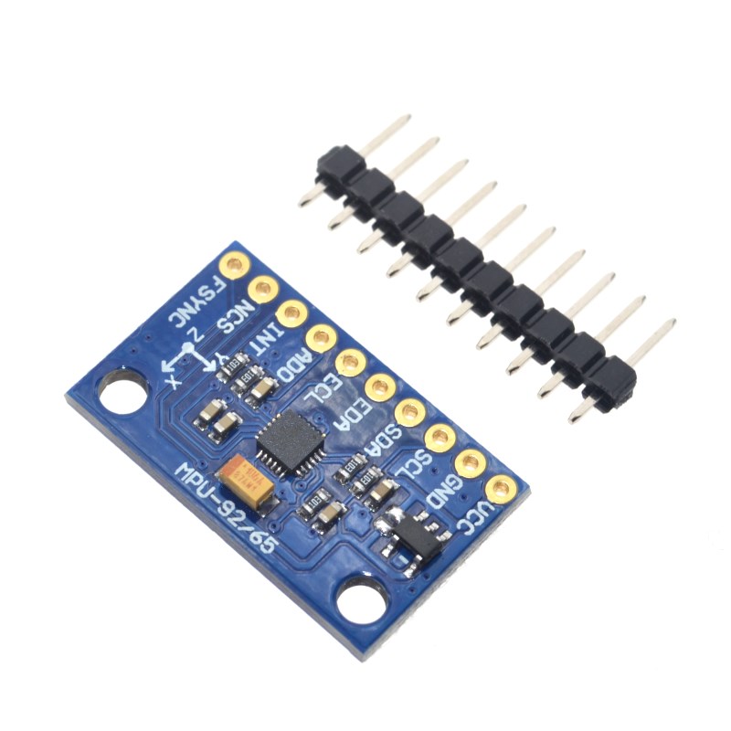
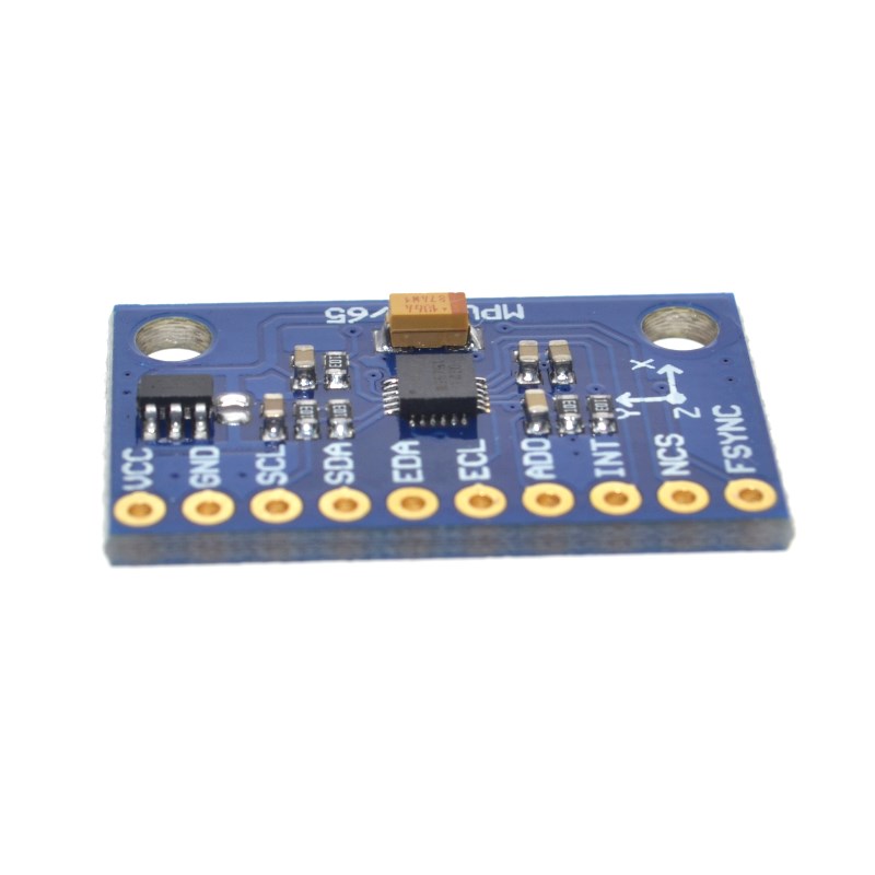
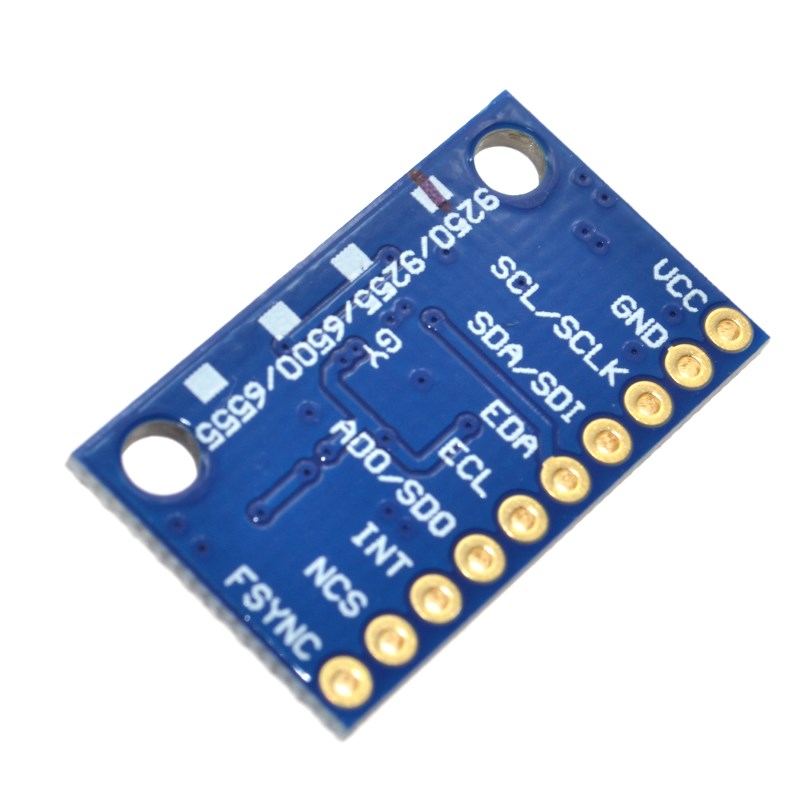
Pinout & Connection Guide
The GY-9250 module features a 7-pin configuration (2.54mm pitch) .
Interface Mode Selection
Wiring Diagrams
I2C Mode (Recommended – Uses 2 pins):
SPI Mode (For higher data rates):
Usage Guide
Important Notes Before Use
-
Magnetometer Not Functional: This refurbished unit has a non-operational magnetometer. You will only have access to gyroscope and accelerometer data (6-axis motion). Do not attempt to read magnetometer registers as they will return invalid data .
-
I2C Address: Default I2C address is 0x68 (when AD0 pin is GND). To change to 0x69, connect AD0 to VCC .
-
SPI vs I2C: Use I2C for simpler wiring and compatibility. Use SPI for higher data rates and when multiple sensors are needed on the same bus (each requires a dedicated CS pin) .
-
Pull-up Resistors: The module includes onboard pull-up resistors, so no external pull-ups are needed for I2C .
Software Setup (Arduino IDE)
Step 1: Install Required Libraries
The MPU-9250 is supported by several libraries. The most popular is the MPU9250 library by bolderflight .
-
Open Arduino IDE → Sketch → Include Library → Manage Libraries
-
Search for “MPU9250”
-
Install the library by bolderflight
Step 2: I2C Address Verification
Before writing code, verify your sensor’s I2C address. Run this scanner sketch:
#include <Wire.h>

void setup() {
  Wire.begin();
  Serial.begin(9600);
  Serial.println("I2C Scanner");
}

void loop() {
  byte error, address;
  int nDevices = 0;

  for(address = 1; address < 127; address++) {
    Wire.beginTransmission(address);
    error = Wire.endTransmission();

    if(error == 0) {
      Serial.print("I2C device found at address 0x");
      if(address < 16) Serial.print("0");
      Serial.println(address, HEX);
      nDevices++;
    }
  }

  if(nDevices == 0) Serial.println("No I2C devices found");
  delay(5000);
}
Expected output: Address 0x68 (or 0x69 if AD0 is tied HIGH).
Step 3: Basic Test Sketch (Gyroscope & Accelerometer Only)
GY-9250 MPU-9250 Basic Read Example
Note: Magnetometer is not functional on this refurbished unit
*/
#include <Wire.h>
#include <MPU9250.h>
MPU9250 mpu;
void setup() {
Serial.begin(115200);
Wire.begin();
if (!mpu.setup(0x68)) {
Serial.println("MPU-9250 sensor not found! Check wiring.");
while (1);
}
mpu.setGyroRange(2000);
mpu.setAccelRange(16);
Serial.println("GY-9250 MPU-9250 Ready (Magnetometer Non-Functional)");
Serial.println("---------------------------------------------------");
}
void loop() {
if (mpu.update()) {
float ax = mpu.getAccelX_mss() / 9.81;
float ay = mpu.getAccelY_mss() / 9.81;
float az = mpu.getAccelZ_mss() / 9.81;
float gx = mpu.getGyroX();
float gy = mpu.getGyroY();
float gz = mpu.getGyroZ();
float temp = mpu.getTemperature_C();
Serial.print("Accel (g): ");
Serial.print(ax); Serial.print(", ");
Serial.print(ay); Serial.print(", ");
Serial.println(az);
Serial.print("Gyro (°/s): ");
Serial.print(gx); Serial.print(", ");
Serial.print(gy); Serial.print(", ");
Serial.println(gz);
Serial.print("Temperature: ");
Serial.print(temp);
Serial.println(" °C");
float pitch = atan2(-ax, sqrt(ay * ay + az * az)) * 180 / PI;
float roll = atan2(ay, az) * 180 / PI;
Serial.print("Pitch: ");
Serial.print(pitch);
Serial.print("°, Roll: ");
Serial.println(roll);
Serial.println("---------------------------------------------------");
}
delay(100);
}
Step 4: Using the Digital Motion Processor (DMP)
The DMP can perform sensor fusion to provide quaternion (3D orientation) output without complex calculations on your microcontroller.
MPU-9250 DMP Example
*/
#include <Wire.h>
#include <MPU9250_WE.h>
MPU9250_WE mpu = MPU9250_WE(&Wire);
void setup() {
Serial.begin(115200);
Wire.begin();
if (!mpu.init()) {
Serial.println("MPU9250 does not respond!");
while (1);
}
if (!mpu.enableDMP()) {
Serial.println("DMP could not be enabled!");
while (1);
}
Serial.println("DMP ready - Outputting quaternion angles");
}
void loop() {
if (mpu.checkNewData()) {
xyzFloat angles = mpu.getAngles();
Serial.print("Yaw: ");
Serial.print(angles.x);
Serial.print("°, Pitch: ");
Serial.print(angles.y);
Serial.print("°, Roll: ");
Serial.println(angles.z);
}
delay(50);
}
Q: Why is the magnetometer not functional on this module?
This is a refurbished unit where the magnetometer component is not operational. You will only have access to 6-axis motion data (gyroscope + accelerometer). This is a known issue with some GY-9250 modules – customer reviews have reported the absence of a functioning magnetometer .
Q: Can I still use this module for drone flight control?
Yes, absolutely. Drone flight controllers primarily rely on gyroscope and accelerometer data for stabilization. The magnetometer is typically used for heading hold (yaw reference), but many drones fly perfectly well without it, especially in acro or rate mode where the pilot controls yaw directly.
Q: What is the difference between I2C and SPI communication?
I2C uses only 2 pins (SDA, SCL) and is simpler to wire, but has a lower maximum data rate. SPI uses 4 pins (SCLK, SDI, SDO, nCS) and offers higher data rates, making it suitable for applications requiring frequent sensor reads. SPI also allows multiple sensors on the same bus with dedicated CS pins .
Q: What is the Digital Motion Processor (DMP) and why is it useful?
The DMP is an onboard processor that can perform sensor fusion (combining gyroscope and accelerometer data) to calculate orientation (quaternion) without burdening your main microcontroller. This frees up your MCU for other tasks and ensures consistent timing for motion processing .
Q: How do I change the I2C address?
The I2C address is controlled by the AD0 pin. When AD0 is connected to GND, the address is 0x68. When AD0 is connected to VCC, the address is 0x69 . This allows two MPU-9250 sensors on the same I2C bus.
Q: Can I use this module with a 5V microcontroller like Arduino Uno?
Yes. The module includes an onboard 3.3V voltage regulator and logic level converters, making it directly compatible with both 3.3V and 5V systems. Connect VCC to 5V and SDA/SCL directly to the I2C pins .
Q: Why are my gyroscope readings drifting over time?
Gyroscopes measure angular velocity, not absolute angle. To get angle, you integrate the rate over time, which accumulates small errors (bias drift). To correct this, you can:
-
Use the DMP, which performs sensor fusion with accelerometer data to correct drift
-
Implement a complementary filter in your own code
-
Periodically reset the gyroscope bias
Q: Can I use multiple GY-9250 modules on the same bus?
For I2C: Only two sensors can share the bus (addresses 0x68 and 0x69). For more than two, you need an I2C multiplexer .
For SPI: You can connect multiple sensors to the same SPI bus, each requiring a dedicated CS (Chip Select) pin from your microcontroller .
Q: How do I calibrate the accelerometer and gyroscope?
Basic calibration can be done by:
-
Gyroscope: Place the sensor stationary on a level surface. Record the average offset on each axis for several seconds. Subtract these offsets from all future readings.
-
Accelerometer: Place the sensor in six orientations (±X, ±Y, ±Z). Record the readings in each orientation to determine scale factors.
Many MPU-9250 libraries include built-in calibration functions.
Q: What is the maximum output data rate?
The maximum output data rate depends on the communication interface and settings:
-
I2C: Up to 400 kHz bus speed, typically 1 kHz output rate
-
SPI: Higher data rates, up to 8 kHz output rate possible
Q: This module works for orientation tracking, but what about heading?
Without a functioning magnetometer, you cannot get absolute heading (direction relative to magnetic north). For heading, you would need a separate compass module or rely on GPS data. However, you can still track relative yaw (rotation around vertical axis) by integrating gyroscope data – though this will drift over time.
Q: How do I verify that the magnetometer is indeed non-functional?
Run an I2C scanner after enabling I2C bypass mode on the MPU-9250. A functional magnetometer would appear at address 0x0C. If this address is not detected, the magnetometer is not responding, confirming it is non-functional .