Product Overview
The High-Power MOSFET Trigger Switch Driver Module is a versatile and robust solid-state switching solution designed to bridge the gap between low-voltage control signals and high-power DC loads. This module acts as an intelligent, high-current relay replacement, allowing your microcontroller (Arduino, Raspberry Pi, ESP32, PLC) to safely and efficiently control devices that draw significant power .
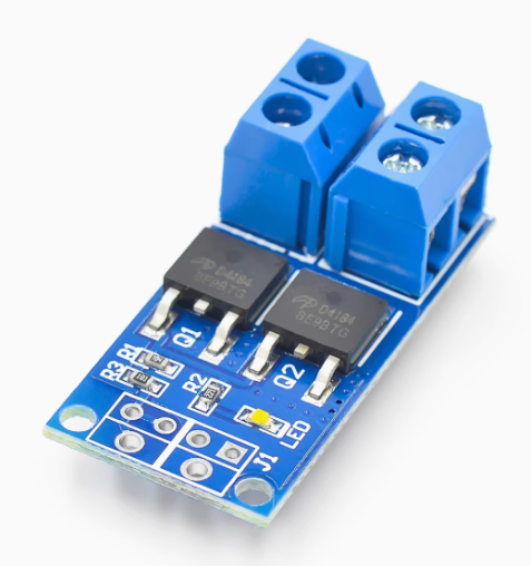
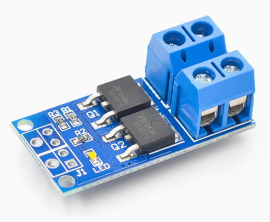
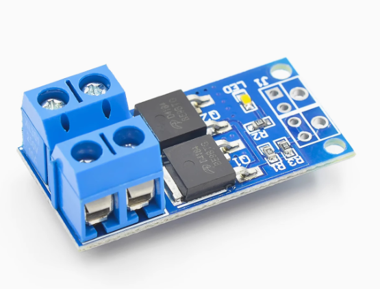
At its core, the module utilizes a dual-MOSFET parallel output design . This configuration significantly reduces internal resistance, allowing for higher current handling with minimal heat generation compared to single-transistor solutions. This “trigger switch” capability means you can use a small 3.3V or 5V signal from a logic device to switch loads up to 30A at 36V .
A key feature of this driver is its full support for Pulse Width Modulation (PWM) signals up to 20kHz . This goes far beyond simple on/off control, enabling smooth and efficient speed regulation of DC motors, stepless dimming of high-power LED lighting, and precise control of other DC-powered actuators and equipment.
Whether you are building an automated lighting system, a robotic platform, a high-power pump controller, or integrating with industrial PLCs, this module provides a simple, reliable, and high-performance interface for all your DC power switching needs .
Key Features
-
High-Current Dual-MOSFET Design: Employs two power MOSFETs in parallel, which lowers the overall on-resistance. This design minimizes power loss and heat, allowing for a higher continuous current rating of 15A to 30A (depending on cooling and model) .
-
Wide Operating Voltage Range: Accepts load voltages from 5V to 36V DC, making it compatible with a vast array of common power supplies, batteries, and DC devices .
-
400W High-Power Capacity: Capable of handling significant power, with a maximum power rating of up to 400W (based on voltage and current ratings), suitable for demanding applications .
-
Versatile Low-Voltage Trigger: The control input accepts a wide range of trigger signals, from 3.3V to 20V . This ensures direct compatibility with virtually all microcontrollers (including 3.3V logic like ESP32 and Raspberry Pi) as well as industrial PLCs and other DC control sources.
-
PWM Speed & Brightness Control: Fully supports 0-20kHz PWM signals . This allows for precise analog-style control, enabling smooth motor speed variation, proportional valve control, and flicker-free LED dimming.
-
Plug-and-Play Simplicity: The module is compact and ready to use, featuring screw terminals for easy and secure connection of high-power wires and a pin header for low-voltage control signals .
-
Wide Operating Temperature: Engineered to perform reliably in various environments, with an operating temperature range of -40°C to +85°C .
-
Isolated Control (Model Dependent): While specifications vary, many high-power modules in this category include optical isolation to protect your sensitive control logic from the high-power load circuit.
Technical Specifications
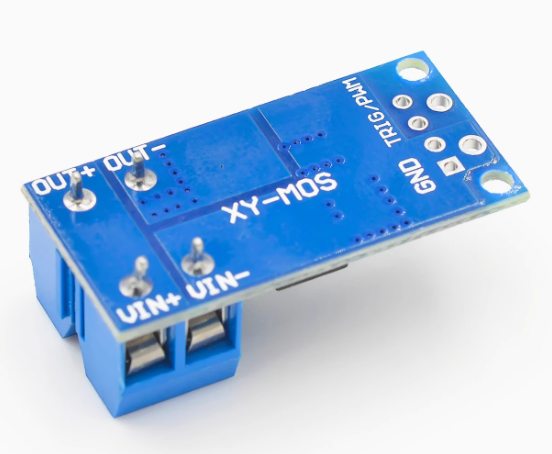
Pinout & Interface Guide
The module features a clear separation between the low-voltage control side and the high-power load side.
Control Side (3/4-Pin Header)
-
SIG (Signal): The trigger input. Apply a DC voltage (3.3V-20V) to turn the MOSFET switch ON and connect the load. Apply 0V to turn it OFF . Sending a PWM signal enables speed or brightness control .
-
VCC / + (Input Voltage for internal driver): This pin powers the module’s internal driver circuitry. It typically accepts a wide voltage range (e.g., 5-18V) and can often be connected directly to your microcontroller’s 5V or 3.3V output, or to a separate power source .
-
GND / – (Ground): Common ground for the control side. This must be connected to the ground of your microcontroller or signal source.
Power Side (Screw Terminals)
-
VIN / V+ (+): The positive input for your external DC power supply (5-36V). Connect the positive lead from your battery or power adapter here .
-
VOUT / V- (-): The switched output. Connect the negative wire of your load (motor, LED strip, etc.) to this terminal. The positive wire of your load must be connected directly to the positive terminal of your external power supply.
Usage Guide
Important Safety Warnings
-
DC ONLY: This module is designed strictly for DC circuits . Never connect AC mains power (e.g., household 110V/220V AC) to this module. It will be destroyed instantly and poses a serious safety hazard.
-
Inductive Loads: When switching motors, solenoids, or pumps (inductive loads), a flyback (snubber) diode is highly recommended across the load’s terminals (cathode/banded end to load positive, anode to load negative) to absorb voltage spikes and protect the module .
-
Heatsinking: At continuous currents above 15A, the MOSFETs will generate significant heat. Proper heatsinking and/or active cooling (a fan) is required to prevent thermal damage .
-
Voltage & Current Limits: Do not exceed the maximum load voltage of 36V or the continuous current rating of the module.
Wiring Guide (Controlling a 12V DC Motor with an Arduino)
Basic Arduino Example Code
This code demonstrates simple on/off control and PWM speed control.
int mosfetPin = 9;
void setup() {
pinMode(mosfetPin, OUTPUT);
}
void loop() {
digitalWrite(mosfetPin, HIGH);
delay(2000);
digitalWrite(mosfetPin, LOW);
delay(2000);
for (int speed = 0; speed <= 255; speed++) {
analogWrite(mosfetPin, speed);
delay(10);
}
for (int speed = 255; speed >= 0; speed--) {
analogWrite(mosfetPin, speed);
delay(10);
}
delay(1000);
}
Q: What is the difference between this "trigger switch" module and a standard MOSFET module?
This module is designed as a complete, high-power switching solution. It typically features a dual-MOSFET parallel design for higher current capacity and lower resistance, and an integrated driver circuit that allows it to accept a wide range of trigger voltages (3.3V-20V) directly . It’s built for high-power, plug-and-play use.
Q: What types of loads can I control with this module?
You can control various DC loads up to 36V, including:
-
DC motors (for speed control via PWM)
-
High-power LED strips and lighting (for dimming)
-
Solenoid valves and relays
-
DC pumps and fans
-
Other DC-powered actuators and resistive loads
Q: Can this module control AC loads (like a household light)?
No, absolutely not. This module is strictly for DC circuits only . It is not designed or safe for AC mains voltage.
Q: Can I use this module with a 3.3V logic controller like a Raspberry Pi or ESP32?
Yes. The control input accepts signals from 3.3V to 20V , making it directly compatible
Q: What is the real-world current limit for this module?
The rating depends heavily on cooling. Many modules are rated for 15A continuous without a heatsink and can reach up to 30A continuous with proper heatsinking and airflow . For long-term reliability, it’s best to operate within the continuous rating for your setup.
Q: Do I need a flyback diode for my motor?
Highly recommended. When switching any inductive load like a motor or solenoid, the collapse of the magnetic field generates a high-voltage spike that can damage the module . Adding an external fast-recovery diode (like a 1N400x or UF400x) across the motor’s terminals is a best practice for long-term reliability.
Q: The module gets hot. Is this normal?
Some heat is normal when switching high currents. If the MOSFETs are too hot to touch, you need better cooling. This means attaching a heatsink and/or providing active airflow.
Q: My load doesn't turn on, even though the control signal is HIGH.
Check the following:
-
Power Supply: Is your external power supply turned on and providing the correct voltage at the VIN terminals?
-
Wiring: Remember, the module switches the ground (negative) side. Ensure the load’s positive wire goes directly to the power supply positive, and the load’s negative wire goes to the module’s VOUT terminal .
-
Ground Loop: Ensure the GND of your external power supply is connected to the GND terminal on the power side of the module to complete the circuit.
Q: The load stays on even when the control signal is set to LOW.
This indicates the MOSFET is not fully turning off. Ensure your microcontroller pin is configured as an OUTPUT and is being driven firmly to LOW (0V) .
Q: My PWM control is jerky or the motor makes a loud noise.
This is often a frequency issue. Try lowering the PWM frequency in your code. Experiment with values from a few hundred Hz to a few kHz for optimal performance with your specific motor.