Product Overview
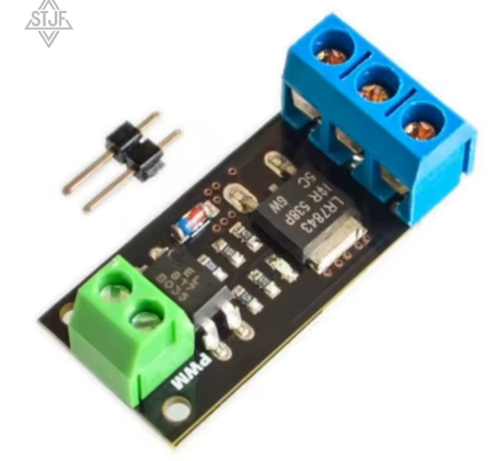
The Industrial-Grade Isolation MOSFET Power Switch Module is a high-performance, solid-state switching solution designed for demanding DC power control applications. Built around a high-quality MOSFET (compatible with the renowned LR7843), this module combines exceptional current handling capability with robust opto-isolation to create a safe and reliable interface between your low-voltage control electronics and high-power DC loads .
At its core, this module utilizes an N-Channel logic-level power MOSFET featuring an ultra-low on-resistance (RDS(on)) of just 3.3mΩ . This extremely low resistance ensures minimal power loss and heat generation, even when switching currents up to 15A continuously . The MOSFET itself is capable of handling peak currents of up to 161A, though practical continuous operation requires proper thermal management .
The key differentiator of this module is its built-in opto-isolation circuit, centered around a PC817 optocoupler . This creates a complete electrical barrier between the input signal (your microcontroller) and the high-power load circuit, protecting your sensitive electronics from dangerous voltage spikes, back-EMF from motors, and ground loop interference . If the MOSFET were to fail catastrophically, the isolation helps ensure that your expensive Arduino, Raspberry Pi, or PLC remains unharmed .
This module is the ideal choice for industrial automation, robotics, high-power lighting control, motor speed regulation, and any application requiring reliable, high-speed switching of DC loads up to 28V . Its compatibility with both 3.3V and 5V logic makes it a versatile building block for modern control systems .
Key Features
-
High-Performance MOSFET (LR7843 Compatible): Utilizes a powerful N-Channel MOSFET with an exceptionally low on-resistance of just 3.3mΩ . This ensures efficient power delivery with minimal heat generation, even at high currents.
-
Industrial-Grade Current Handling: Capable of switching 15A continuously with a 12V load (based on module design and thermal performance) . The MOSFET itself is rated for peak currents up to 161A, providing a massive safety margin for surge loads .
-
Robust Opto-Isolation: Features a built-in PC817 optocoupler that provides galvanic isolation between the control signal and the power circuit . This critical feature:
-
Protects microcontrollers from back-EMF and voltage spikes
-
Eliminates ground loop interference
-
Enhances noise immunity in industrial environments
-
Wide Logic Voltage Compatibility: Accepts control signals from 2.5V to 20V, making it directly compatible with 3.3V microcontrollers (ESP32, Raspberry Pi Pico), 5V systems (Arduino), and even 12V-24V industrial PLCs without any additional components .
-
PWM Compatible for Analog Control: Fully supports high-speed PWM signals, enabling smooth and efficient speed control of DC motors or stepless dimming of high-power LED lighting .
-
Active HIGH Logic: Simple and intuitive control—apply a HIGH logic signal (or PWM) to turn the MOSFET ON and connect the load; apply LOW to turn it OFF .
-
Visual Status Indicator: An onboard LED provides immediate visual confirmation when the MOSFET is switched on, simplifying troubleshooting and operation monitoring .
-
Flexible Connection Options: Features solder pads for both pin headers and screw terminals, allowing you to configure the module for breadboard prototyping or permanent installations .
-
Compact & Mountable Design: Small footprint with two 2mm mounting holes for secure integration into enclosures or control panels .
-
Parallel Operation Capability: Modules can be connected in parallel to further increase overall power handling capacity for extreme applications .
Technical Specifications
Pinout & Interface Guide
The module is clearly divided into a low-voltage control side and a high-voltage power side.
Control Side (2-Pin Header)
-
PWM / SIG (Signal): The control input. Apply a HIGH logic signal (2.5V-20V) to turn the MOSFET ON. Apply LOW (0V) to turn it OFF . Sending a PWM signal enables speed or brightness control .
-
GND (Ground): Common ground for the control side. Connect to a GND pin on your microcontroller. This ground is electrically isolated from the load ground .
Power Side (3-Pin Screw Terminal)
-
+ (Positive Input): The positive input for your external DC power supply (6-28V). Connect the positive lead from your battery or power supply here .
-
LOAD (Switched Output): The switched output. Connect the negative wire of your load (motor, LED strip, etc.) to this terminal. The MOSFET acts as a switch between this terminal and the power supply ground .
-
– (Negative Input): The negative input for your external DC power supply. Connect the negative (ground) lead from your power supply here .
Important Wiring Note: This module is designed for low-side switching. The positive wire of your load must be connected directly to the + terminal of your external power supply. The module switches the ground (negative) side of the circuit .
Theory of Operation
Understanding how this module works helps in troubleshooting and optimizing its use.
-
Control Signal Input: Your microcontroller sends a signal to the PWM/SIG pin. This pin has a 1kΩ series resistor to limit current to the internal optocoupler LED .
-
Optocoupler Activation: When the signal is HIGH, it illuminates the LED inside the PC817 optocoupler. This light activates the phototransistor on the other side of the isolation barrier .
-
Gate Biasing: The activated phototransistor completes a circuit, creating a voltage divider (typically using two 4.7kΩ resistors) that biases the MOSFET’s gate to approximately 50% of the load power supply voltage . For a 12V supply, the gate gets about 6V, which is sufficient to fully turn on the logic-level MOSFET.
-
Load Switching: When the MOSFET turns on, it connects the LOAD terminal to the power supply ground (– terminal), completing the circuit and powering your device .
-
Visual Indication: The completed circuit also provides a ground path for the onboard status LED, which lights up to show that the MOSFET is conducting .
-
Deactivation: When the control signal goes LOW, the optocoupler LED turns off. The phototransistor opens, and a pull-down resistor (4.7kΩ) quickly drains any remaining charge from the MOSFET’s gate, turning it off and disconnecting the load .
Usage Guide
Important Safety Warnings
-
DC ONLY: This module is designed strictly for DC circuits . Never connect AC mains power (e.g., household 110V/220V AC) to this module. It will be destroyed instantly and poses a serious safety hazard .
-
Inductive Loads Require a Flyback Diode: When controlling inductive loads like motors, solenoids, or relays, you MUST add an external flyback (snubber) diode across the load’s terminals (cathode/banded end to load positive, anode to load negative). The module does not include this diode, and switching inductive loads without it will eventually damage the MOSFET .
-
Thermal Management: While the MOSFET is rated for very high peak currents, the small PCB has minimal heatsinking capability . For continuous operation above 5-10A, provide active cooling (a fan) or attach a small heatsink to the MOSFET. Keep the MOSFET temperature below 80°C for long-term reliability .
-
Power Supply Voltage: Note the minimum supply voltage requirement. The MOSFET’s gate is driven to 50% of the load supply voltage. At lower voltages, the gate may not turn on hard enough, causing increased resistance and heat. For currents above a few amps, a minimum 9V supply is recommended .
Wiring Guide (Controlling a 12V DC Motor with Arduino)
Basic Arduino Example Code
This code demonstrates simple on/off control and PWM speed control.
int mosfetPin = 9;
int speed = 0;
void setup() {
pinMode(mosfetPin, OUTPUT);
}
void loop() {
digitalWrite(mosfetPin, HIGH);
delay(2000);
digitalWrite(mosfetPin, LOW);
delay(2000);
for (speed = 0; speed <= 255; speed++) {
analogWrite(mosfetPin, speed);
delay(10);
}
for (speed = 255; speed >= 0; speed--) {
analogWrite(mosfetPin, speed);
delay(10);
}
delay(1000);
}
Q: What does "LR7843 compatible" mean?
It means the module is designed to be functionally equivalent and pin-compatible with modules using the specific LR7843 MOSFET. It utilizes a MOSFET with similar or better specifications (like ultra-low on-resistance) and the same proven opto-isolated circuit topology
Q: What is the advantage of this module over a simple non-isolated MOSFET?
The key advantage is safety and noise immunity. The opto-isolation creates a complete electrical barrier between your sensitive and expensive microcontroller and the high-power, potentially noisy load circuit . This protects your controller from dangerous voltage spikes (back-EMF) and eliminates ground loop problems
Q: What types of loads can I control with this module?
You can control various DC loads up to 28V, including:
-
DC motors (for speed control via PWM)
-
High-power LED strips and lighting (for dimming)
-
Solenoid valves and relays
-
DC pumps and fans
-
Heating elements
Q: Can this module control AC loads (like a household light)?
No, absolutely not. This module is strictly for DC circuits only . The MOSFET is designed for DC switching and cannot block AC current
Q: Can I use this module with a 3.3V controller like a Raspberry Pi or ESP32?
Yes. The control input accepts signals from 2.5V to 20V , making it directly compatible with both 3.3V and 5V logic levels
Q: What is the real-world current limit for this module?
The practical, continuous current is limited by the module’s small PCB and lack of a heatsink. It is rated for 15A continuous with a 12V load . For long-term reliability, operating at 10A or less is recommended unless you provide active cooling . The MOSFET itself is rated for much higher peak currents (161A), but the module cannot dissipate the heat from such currents continuously
Q: Do I need a flyback diode for my motor?
Yes, absolutely required. The module does not include one . When switching any inductive load (motor, solenoid, pump), the collapse of the magnetic field generates a high-voltage spike that can instantly destroy the MOSFET. An external flyback diode (e.g., 1N4007) connected across the load terminals is essential for long-term reliability
Q: Why is a minimum 9V power supply recommended for high currents?
The module’s circuit biases the MOSFET gate at 50% of the load power supply voltage . To fully turn on a logic-level MOSFET and achieve its lowest possible on-resistance, you typically need 4.5V to 10V on the gate. At 6V, the gate voltage is only 3V, which may not turn the MOSFET on hard enough, leading to higher resistance and excessive heat. For currents above a few amps, a 9V or higher supply ensures the MOSFET switches efficiently
Q: The module gets hot. Is this normal?
Some heat is normal when switching high currents. The temperature test data shows that at 15A continuous, the MOSFET can reach nearly 100°C without a heatsink . If it’s too hot to touch, you need better cooling (a fan or small heatsink) or to reduce the current. Keep it under 80°C for best reliability
Q: Can I parallel multiple modules for higher current?
Yes. These modules are designed such that they can be connected in parallel to increase total current handling capacity . Connect all control signals together and all power connections appropriately.
Q: My load doesn't turn on, even though the control signal is HIGH.
Follow this checklist:
-
Check Wiring: Remember, this is a low-side switch. Ensure the load’s positive wire goes directly to the power supply + terminal, and the load’s negative wire goes to the module’s LOAD terminal .
-
Check Power Supply: Verify your external power supply is on and providing the correct voltage at the + and – terminals (should be at least 6V) .
-
Check Signal Ground: Ensure the control-side GND is connected to your microcontroller’s ground.
-
Check Voltage: Measure the voltage at the SIG pin with your microcontroller; it should be HIGH (3.3V/5V).
Q: The load stays on even when the control signal is set to LOW.
This indicates the MOSFET is not fully turning off. Ensure your microcontroller pin is configured as an OUTPUT and is being driven firmly to LOW (0V) . A failing optocoupler or a shorted MOSFET could also cause this.
Q: My PWM control is jerky or the motor makes a loud noise.
This is often a frequency issue. Try lowering the PWM frequency in your code. Experiment with values from a few hundred Hz to a few kHz for optimal performance with your specific motor.
Q: Is the signal ground and load ground the same?
No. Due to the opto-isolation, the signal ground (from your microcontroller) and the load power ground are electrically isolated and are not connected on the module . Do not connect them together externally.