Product Overview
The L298 High-Power Dual H-Bridge Motor Driver is an industrial-grade motor control module designed for high-current applications requiring robust performance and reliability. Unlike standard L298N modules limited to 2A, this high-power variant leverages the L298 logic architecture with enhanced power circuitry to deliver a continuous 7A per channel and a total output power of 160W .
This module serves as the ideal interface between your microcontroller (Arduino, PLC, STM32, Raspberry Pi) and high-power DC motors, linear actuators, or industrial automation equipment. It features optocoupler isolation between the control logic and high-power stages, protecting your sensitive microcontroller from electrical noise, voltage spikes, and ground loops commonly found in industrial environments .
Whether you are building heavy-duty robotic platforms, automated conveyor systems, electric vehicle prototypes, or industrial machinery, this driver provides the power handling and noise immunity required for reliable operation.
Key Features
-
High-Current Dual H-Bridge: Drives two DC motors simultaneously with a rated continuous output current of 7A per channel and peak current capacity of 50A (transient), enabling control of high-torque motors and actuators .
-
160W Total Output Power: Capable of delivering substantial power to your motors, with support for 12V motors up to 40W and 24V motors up to 115W continuously .
-
Optocoupler Isolation: Features signal optocoupler isolation between the logic inputs and the power stage. This critical feature provides:
-
Protection for microcontrollers from back-EMF and voltage spikes
-
Elimination of ground loop interference
-
Enhanced noise immunity in industrial environments
-
Wide Operating Voltage Range: Accepts motor supply voltages from 6.5V to 27V, making it compatible with 12V, 18V, and 24V industrial motor systems .
-
Comprehensive Protection Circuitry:
-
Undervoltage Protection: Prevents module damage during brownout conditions by disabling outputs when voltage drops too low
-
TVS Protection: High-power transient voltage suppression diodes absorb voltage spikes and enhance EMC performance
-
Electrostatic Discharge (ESD) Circuit: Protects against static damage during handling and operation
-
PWM Speed Control: Enable signal terminals (ENA/ENB) accept PWM signals for precise speed regulation, with a supported frequency range of 0-10kHz and minimum pulse width of 10μs .
-
Wide Logic Compatibility: Control signal voltage range of 3V-6.5V ensures compatibility with both 5V microcontrollers (Arduino) and 3.3V systems (ESP32, Raspberry Pi Pico) .
-
Industrial Temperature Range: Rated for operation from -25°C to +80°C, suitable for demanding environments and outdoor applications .
Technical Specifications
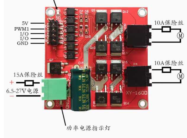
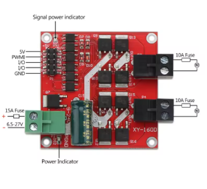
Pinout & Interface Guide
Power Terminals
-
VCC (Power Input): Main motor power supply terminal. Connect a 6.5V-27V DC power source capable of supplying required motor current. Do not exceed 27V .
-
GND: Common ground for both power and logic circuits. Must be connected to power supply negative terminal and microcontroller ground.
Motor Outputs
-
Motor A Terminals (OUT1, OUT2): Connect your first DC motor here. Polarity determines initial rotation direction.
-
Motor B Terminals (OUT3, OUT4): Connect your second DC motor here.
Control Signal Pins
-
ENA (Enable A): PWM input for Motor A speed control. Accepts 0-10kHz PWM signals .
-
IN1, IN2: Direction control inputs for Motor A.
-
IN3, IN4: Direction control inputs for Motor B.
-
ENB (Enable B): PWM input for Motor B speed control.
Usage Guide
Important Pre-Operation Requirements
Fuse Recommendations:
-
Power Input: Connect a 15A fuse in series with the power supply input to protect against overcurrent conditions .
-
Motor Outputs: Connect 10A fuses in series with each motor output to protect the module and motors from short circuits .
Power Supply Requirements:
Control Logic Table (DC Motor)
Note 1: For this industrial module, setting both IN pins LOW results in braking action, unlike standard L298N modules which typically coast in this state. Refer to module specifications or test with your specific unit .
(Same logic applies to Motor B using ENB, IN3, and IN4)
Critical Operating Guidelines
Direction Reversal:
When switching between forward and reverse, you must:
-
Apply braking for at least 0.1 seconds
-
Wait for the motor to stop completely
-
Then apply the reverse signal
Failure to observe this sequence may damage the drive module due to high inrush currents .
Power-Down Protection:
When the drive module is powered down, do not allow the motor to spin at high speed. The motor will act as a generator, producing back-EMF that can burn the drive module. For applications requiring free-spinning when powered off, connect a relay (NO and COM terminals) in series with the motor output, with the relay coil connected to the same power supply as the driver .
Typical Wiring to Arduino (24V Industrial Motor Setup)
Q: What is the difference between this high-power L298 module and the common L298N module?
There are several key differences:
-
Current Capacity: Standard L298N modules handle 2A continuous; this module handles 7A continuous per channel .
-
Isolation: This module features optocoupler isolation between logic and power stages; standard modules do not .
-
Protection: Includes undervoltage protection, TVS diodes, and ESD protection circuits not found on basic modules .
-
Application: Designed for industrial and high-power use, while standard L298N targets hobby robotics.
Q: Can I drive a 24V industrial motor with this module?
Yes. The module supports motor supply voltages up to 27V. For 24V motors, the maximum continuous power is 115W (motors rated at 115W or below with current ≤7A)
Q: What types of motors can I use with this driver?
This driver is designed for brushed DC motors (two of them). It can also drive bipolar stepper motors using both H-bridges. It is not suitable for brushless DC motors (BLDC) or servo motors without additional control circuitry.
Q: Can I use this with a 3.3V microcontroller like an ESP32?
Yes. The control signal voltage range is 3V-6.5V, making it directly compatible with 3.3V logic levels without level shifters
Q: Why are fuses strongly recommended?
This module is designed for high power (up to 160W). Without proper fusing:
-
A short circuit at the motor output can draw peak currents up to 50A, instantly destroying the module
-
Power supply reverse polarity can damage the module instantly
-
Motor stalls can cause sustained overcurrent conditions
The recommended fuses (15A input, 10A outputs) protect your investment and ensure safety.
Q: What happens if I exceed 27V on the power input?
Exceeding 27V will likely burn out the module immediately. The voltage limit is strict and must not be violated, even momentarily
Q: The module has undervoltage protection. What triggers it?
The undervoltage protection activates when the power supply voltage drops below the minimum operating threshold (typically around 6V). This commonly happens when:
-
The power supply is too weak for the motor startup current
-
Battery voltage sags under heavy load
-
There is excessive resistance in power wiring
When triggered, the module will pause output until voltage recovers
Q: Can I connect two motors that draw more than 7A total?
The total output power is 160W. You must ensure that neither channel exceeds 7A continuously, even if the other channel is unused. The 7A rating is per channel, not shared, but the module’s total power dissipation must be considered
Q: My motors run weakly or stop during startup. What's wrong?
This is typically a power supply issue:
-
Your power supply may not provide enough startup current (should be at least 2× motor rated current)
-
Check for voltage drop under load at the VCC terminal
-
Verify all fuses are intact and connections are tight
-
Ensure wiring gauge is sufficient for the current
Q: What is the correct procedure for changing motor direction?
Critical safety procedure:
-
Stop the motor (set ENA LOW or apply brake)
-
Wait at least 0.1 seconds for the motor to stop completely
-
Then change the IN1/IN2 states to the new direction
-
Reapply PWM signal
Reversing while the motor is still spinning can cause current spikes that damage the module
Q: The module works but gets warm. Is this normal?
At 7A continuous current, the power stage will generate significant heat. The module is designed to handle this within its -25°C to +80°C operating range. Ensure adequate airflow around the module and do not enclose it in a non-ventilated space without considering thermal management
Q: What happens if I short the motor outputs?
Shorting the motor outputs can draw peak currents up to 50A, which will almost certainly destroy the module if not protected by fuses. Always use the recommended 10A fuses on motor outputs
Q: The LEDs are on, but motors don't move.
Check:
-
Enable signals: Ensure ENA/ENB are receiving PWM signals (not left floating)
-
Power supply voltage: Verify VCC is within 6.5V-27V
-
Fuses: Check if input or output fuses have blown
-
Undervoltage protection: If power supply is weak, the module may be cycling in and out of protection
-
Ground connections: Ensure all grounds are properly connected
Q: The motor only runs in one direction.
Verify:
-
Your code is correctly setting both IN1 and IN2 to opposite states (HIGH/LOW or LOW/HIGH)
-
The control signals are actually reaching the IN pins (check wiring)
-
The module hasn’t been damaged by improper reversal (see procedure above)
Q: The module suddenly stopped working and won't restart.
Possible causes:
-
Overvoltage: Power supply may have exceeded 27V
-
Short circuit: Motor output may have shorted without fuse protection
-
Back-EMF damage: Motor may have been spinning when power was removed
-
Overheating: Module may have exceeded maximum temperature if airflow was insufficient