

Specification
- Working Voltage: 5V ~ 12V
- Motor controller: L298P, drives 2 DC motors or 1 stepper motor
- Max current: 2A per channel or 4A max (with external power supply)
- Current sensing: 1.65V/A
Features
- Free running stop and brake function.
- You can also measure the motor current absorption of each motor.
About power
- The Motor Shield must be powered only by an external power supply.
- Because the L298 IC mounted on the shield has two separate power connections,
- one for the logic and one for the motor supply driver. The required motor current often exceeds the maximum USB current rating.
- External (non-USB) power can come either from an AC-to-DC adapter (wall-wart) or battery.
- The adapter can be connected by plugging a 2.1mm center-positive plug into the for board power jack on
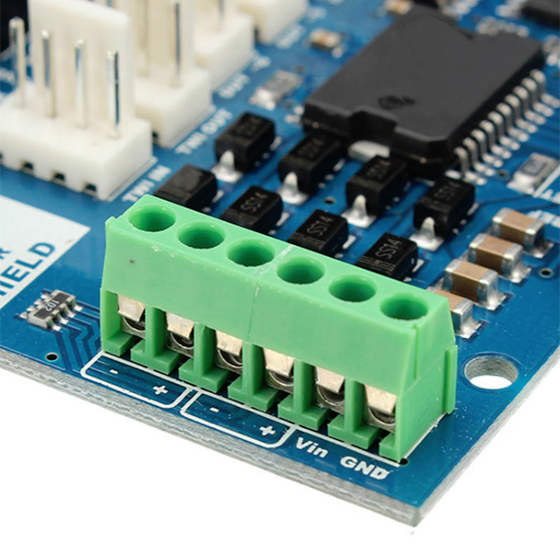
- which the motor shield is mounted or by connecting the wires that lead the power supply to the Vin and GND screw terminals,
- taking care to respect the polarities.
- To avoid possible damage to the for board on which the shield is mounted,
- we recommend using an external power supply that provides a voltage between 7 and 12V.
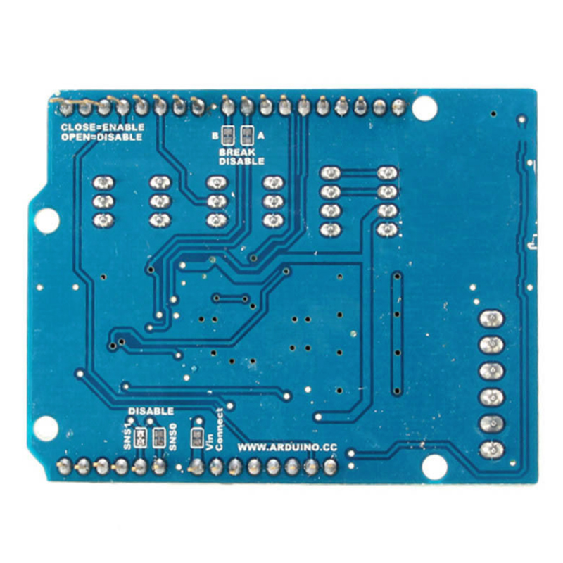
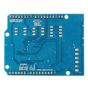
- If your motor require more than 9V we recommend that you separate the power lines of the shield and the for board on
- which the shield is mounted. This is possible by cutting the “Vin Connect” jumper placed on the back side of the shield.
- The absolute limit for the Vin at the screw terminals is 18V.
Pin Description
| Function | Pins Per Ch. A | Pins Per Ch. B |
| Direction | D12 | D13 |
| PWM | D3 | D11 |
| Brake | D9 | D8 |
| Current Sensing | A0 | A1 |
If you don’t need the Brake and the Current Sensing and you also need more pins for your application you can disable this features by cutting the respective jumpers on the back side of the shield.
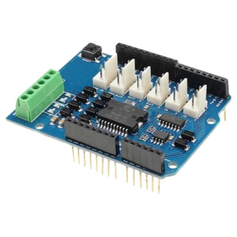
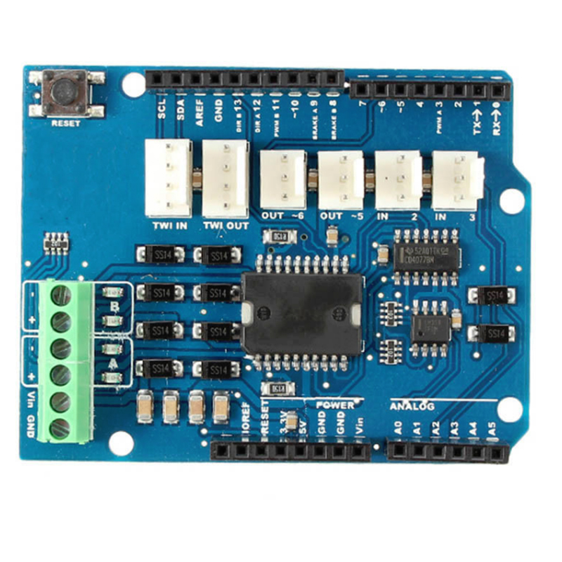
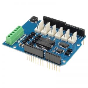
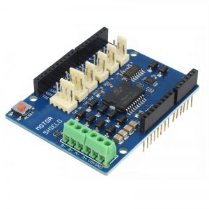
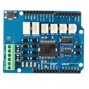
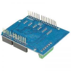
The additional sockets on the shield are described as follow
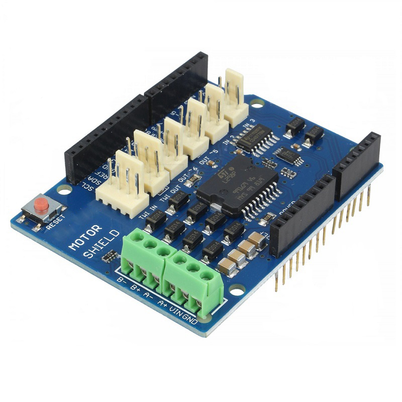
Screw terminal to connect the motors and their power supply.
2 TinkerKit connectors for two Analog Inputs (in white), connected to A2 and A3.
2 TinkerKit connectors for two Aanlog Outputs (in orange in the middle), connected to PWM outputs on pins D5 and D6.
2 TinkerKit connectors for the TWI interface (in white with 4 pins), one for input and the other one for output.
Motors connections
Brushed DC motor. You can drive two Brushed DC motors by connecting the two wires of each one in the (+) and (-) screw terminals for each channel A and B. In this way you can control its direction by setting HIGH or LOW the DIR A and DIR B pins, you can control the speed by varying the PWM A and PWM B duty cycle values. The Brake A and Brake B pins, if set HIGH, will effectively brake the DC motors rather than let them slow down by cutting the power. You can measure the current going through the DC motor by reading the SNS0 and SNS1 pins. On each channel will be a voltage proportional to the measured current, which can be read as a normal analog input, through the function analogRead() on the analog input A0 and A1. For your convenience it is calibrated to be 3.3V when the channel is delivering its maximum possible current, that is 2A.
Packing Included
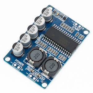
1 x L298P Motor Driver Module