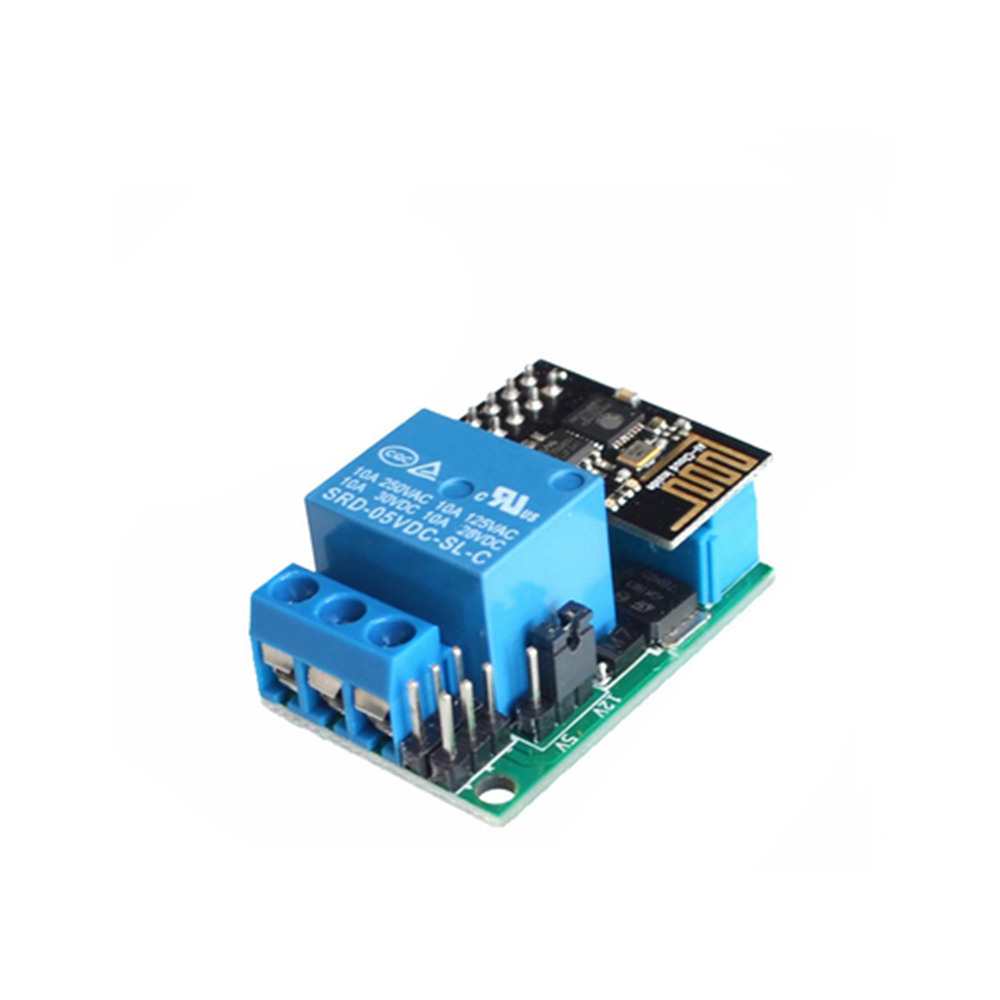
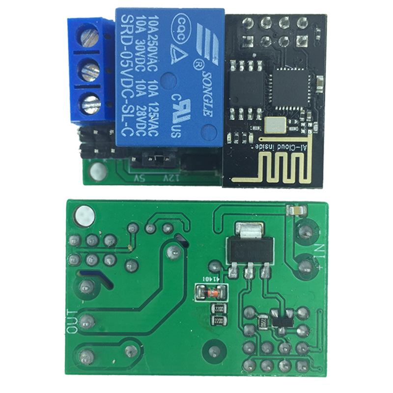
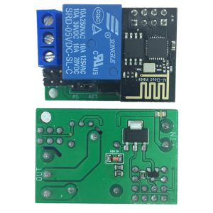
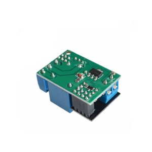
M1 IoT Smart Switch – DC 5-12V 10A 0.5W Voice Control, Momentary/Latch Mode, DIY Home Automation (Open for Secondary Development)

SKU: FA2179
Relay Rating

10A (DC 5-12V load)

Standby Power

0.5W

Operating Voltage

DC 5-12V

Control Modes

Momentary / Latch (selectable)

Voice Control

Compatible with voice recognition modules

Trigger Input

External signal or voice command

Terminal Type

Screw terminals

Development

Open for secondary development

The M1 IoT Smart Switch is a compact, versatile relay control module designed for DIY home automation, voice control projects, and secondary development. It combines a high-current relay output with voice control capability and flexible operating modes, all in a board that is open for customization and integration into larger systems.

At the heart of the module is a 10A relay capable of switching loads up to DC 5-12V at 0.5W standby power consumption. This makes it suitable for controlling lamps, fans, small motors, solenoid valves, and other household or commercial devices. The relay output provides isolated switching, protecting your control circuit from the load’s electrical characteristics.

The module supports voice control, allowing you to activate or deactivate the relay through voice commands when paired with a compatible voice recognition module or microcontroller. This opens up hands-free control possibilities for lighting, appliances, and accessibility applications.

Two operating modes are available: Momentary mode (the relay is active only while the trigger signal is present) and Latch mode (the relay toggles on and off with each trigger). The mode is selectable via onboard jumper or solder bridge, giving you flexibility to match the module’s behavior to your application.

This module is open for secondary development, meaning the firmware and hardware design are accessible for customization. Whether you want to integrate it into a larger automation system, add wireless connectivity, or modify its behavior for a specific use case, the M1 provides a flexible foundation.

The compact form factor and screw terminals make installation straightforward. The module can be powered from a DC 5-12V supply and integrates easily into existing projects. Whether you are a maker building a smart home prototype, a student learning about relay control and IoT concepts, or a business purchasing in bulk for product development, the M1 IoT Smart Switch offers a practical, customizable solution.


Features

  • 10A high-current relay output — Switches loads up to DC 5-12V at 10A for lamps, fans, motors, and more.

  • Voice control compatible — Works with voice recognition modules and microcontrollers for hands-free operation.

  • Momentary and Latch modes — Selectable via jumper or solder bridge to match your application.

  • Open for secondary development — Firmware and hardware accessible for customization and integration.

  • Low standby power consumption — 0.5W standby for energy-efficient operation.

  • Compact form factor — Small footprint suitable for embedding into enclosures and projects.

  • Screw terminal connections — Secure wiring for power, input, and relay output.

  • DIY home automation ready — Ideal for smart home prototypes, IoT projects, and custom control systems.


Technical Specifications 

# Parameter Specification
1 Relay Rating 10A (DC 5-12V load)
2 Standby Power 0.5W
3 Operating Voltage DC 5-12V
4 Control Modes Momentary / Latch (selectable)
5 Voice Control Compatible with voice recognition modules
6 Trigger Input External signal or voice command
7 Terminal Type Screw terminals
8 Development Open for secondary development

Usage

Getting Started

  1. Power the module — Connect a DC 5-12V supply to the VCC and GND terminals.

  2. Select the operating mode — Use the onboard jumper or solder bridge to choose Momentary or Latch mode.

  3. Connect the trigger source — Wire your trigger signal (microcontroller GPIO, voice recognition module output, or manual switch) to the trigger input terminal.

  4. Connect the load — Wire the device you want to control to the relay output terminals, observing the normally-open (NO) and normally-closed (NC) markings.

  5. Test the circuit — Apply a trigger signal. The relay should click and the load should activate according to the selected mode.

Mode Descriptions

Mode Behavior Use Case
Momentary Relay active only while trigger is present Doorbell, jogging, push-to-talk
Latch Relay toggles on/off with each trigger Light switch, on/off control

Typical Applications

  • DIY home automation — Control lamps, fans, and appliances with voice or manual triggers.

  • Voice-controlled lighting — Pair with a voice recognition module for hands-free light control.

  • IoT prototyping — Integrate into larger smart home systems with added wireless modules.

  • Accessibility projects — Voice or switch-based control for users with limited mobility.

  • Industrial control — Simple relay switching for equipment and processes.

  • Educational projects — Teaching relay control, voice recognition, and IoT concepts.

  • OEM product development — Customizable foundation for commercial products.

Notes for Business Buyers

  • Open for secondary development — Firmware and hardware accessible for customization and product differentiation.

  • Voice control capability — Ready for integration with voice recognition modules.

  • Dual operating modes — One module adapts to multiple control requirements.

  • Suitable for bulk purchasing — Ideal for smart home integrators, product developers, and educational institutions.

Q: What is the maximum load this module can switch?

The relay is rated for 10A at DC 5-12V. For inductive loads like motors, keep the load current below 60–70% of the rated value for reliable operation.

Q: How does voice control work with this module?

The module can be triggered by a voice recognition module or microcontroller that outputs a control signal. When the signal is received, the relay activates according to the selected mode.

Q: What is the difference between Momentary and Latch mode?

Momentary: the relay is active only while the trigger signal is present. Latch: the relay toggles on and off with each trigger signal.

Q: How do I change the operating mode?

Use the onboard jumper or solder bridge to select between Momentary and Latch mode. Refer to the product markings or documentation for the specific configuration.

Q: What does "Open for Secondary Development" mean?

It means the firmware and hardware design are accessible for customization. You can modify the behavior, add wireless connectivity, or integrate it into a larger system.

Q: What is the standby power consumption?

The module consumes approximately 0.5W in standby mode, making it suitable for always-on applications.

Q: Can I control AC loads with this module?

This module is designed for DC loads up to 12V. For AC load switching, a different relay module rated for AC voltage is required.

Q: Can I connect this module directly to an Arduino or ESP32?

Yes. The trigger input accepts standard logic-level signals, making it compatible with Arduino, ESP32, and other microcontrollers.

Q: Does the module come with firmware installed?

The module ships with basic firmware for relay control. For secondary development, you can reprogram or modify the firmware as needed.

Q: Can I purchase in bulk for a school or company?

Yes. This module is suitable for both individual users and business purchasing, including smart home integrators, product developers, and educational institutions.