Product Overview
The MCU-117 High-Precision 9-Axis Motion Tracking Module is a powerful 10-degree-of-freedom (10DOF) inertial measurement unit (IMU) that combines a 9-axis MPU9250 sensor with a high-precision MS5611 barometer on a single compact board. This module is designed for applications requiring accurate orientation, altitude, and motion tracking, including drones, robotics, variometers, and navigation systems .
At its core, the MCU-117 integrates the InvenSense MPU9250 — a complete 9-axis motion tracking device featuring a 3-axis gyroscope, 3-axis accelerometer, and a 3-axis magnetometer — alongside the Measurement Specialties MS5611 high-resolution barometric pressure sensor . This combination provides a true 10DOF sensing solution (gyro + accelerometer + magnetometer + barometer) for comprehensive motion and environmental monitoring.
The module supports both I2C and SPI communication protocols, giving you flexibility to interface with a wide range of microcontrollers including Arduino, ESP32, STM32, and Raspberry Pi. Its compact footprint and low power consumption make it ideal for space-constrained and battery-powered applications such as quadcopter flight controllers, autonomous robots, variometers for paragliding, and wearable tracking devices .
Key Features
-
Complete 10-DOF Sensing: Combines 9-axis motion tracking (3-axis gyro + 3-axis accel + 3-axis magnetometer) with MS5611 barometric pressure sensor for altitude measurement .
-
MPU9250 9-Axis MEMS Sensor: Integrates gyroscope, accelerometer, and magnetometer on a single chip with 16-bit ADC output for high-resolution motion tracking .
-
MS5611 High-Precision Barometer: Ultra-low power barometric pressure sensor with 24-bit ADC, capable of altitude resolution down to 10cm. Ideal for variometers and altitude hold applications .
-
Selectable Communication Interfaces: Supports both I2C and SPI communication protocols, allowing flexible integration with various microcontrollers .
-
Wide Measurement Ranges:
-
Gyroscope: ±250, ±500, ±1000, ±2000 dps (degrees per second)
-
Accelerometer: ±2g, ±4g, ±8g, ±16g
-
Magnetometer: ±4800µT
-
Built-in Digital Motion Processor (DMP): Onboard DMP can perform sensor fusion to output quaternion orientation data, offloading processing from your main microcontroller .
-
Wide Operating Voltage: Operates from 3.3V to 5V DC, compatible with both 3.3V (ESP32, Raspberry Pi) and 5V (Arduino) systems.
-
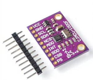
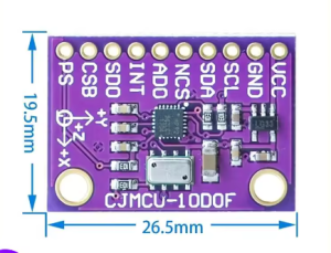
Compact Design: Small module size with 2.54mm pin spacing for easy breadboard integration.
Technical Specifications
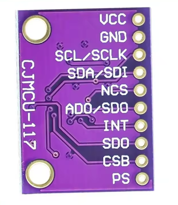
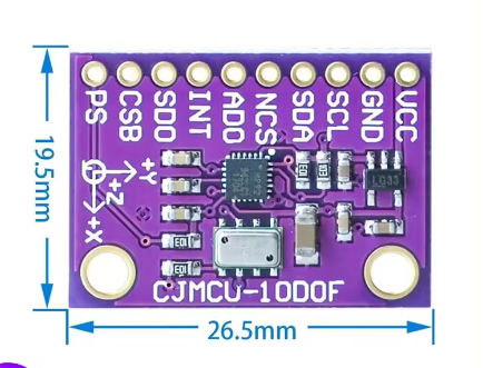
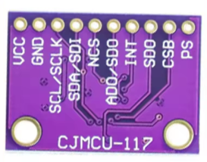
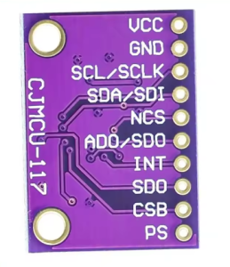
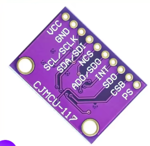
Pinout & Connection Guide
Pin Definitions
I2C Mode Wiring (Recommended – Uses 2 pins)
For I2C communication, connect nCS to VCC (HIGH) to disable SPI mode. The default I2C address of the MPU9250 is 0x68 (or 0x69 if AD0 is pulled HIGH).
I2C Address Configuration
SPI Mode Wiring (For higher data rates)
Usage Guide
Software Setup (Arduino IDE)
Step 1: Install Required Libraries
The MCU-117 is supported by several libraries. The most common libraries are:
-
MPU9250 by bolderflight – Comprehensive library supporting both I2C and SPI
-
MPU9250_WE by wollewald – Includes DMP support
-
Kris Winer’s MPU9250 library – Feature-rich with sensor fusion (available on GitHub)
Install via Arduino Library Manager:
-
Open Arduino IDE → Sketch → Include Library → Manage Libraries
-
Search for “MPU9250”
-
Install your preferred library
Step 2: I2C Address Verification
Run this I2C scanner to verify your sensor’s address before writing code :
#include <Wire.h>

void setup() {
  Wire.begin();
  Serial.begin(9600);
  Serial.println("\nI2C Scanner");
}

void loop() {
  byte error, address;
  int nDevices = 0;

  for(address = 1; address < 127; address++) {
    Wire.beginTransmission(address);
    error = Wire.endTransmission();

    if(error == 0) {
      Serial.print("I2C device found at address 0x");
      if(address < 16) Serial.print("0");
      Serial.println(address, HEX);
      nDevices++;
    }
  }

  if(nDevices == 0) Serial.println("No I2C devices found");
  delay(5000);
}
Expected output: Address 0x68 for MPU9250 and 0x77 or 0x76 for MS5611 .
Step 3: Basic MPU9250 Read Example
MCU-117 Basic MPU9250 Read Example
*/
#include <Wire.h>
#include <MPU9250.h>
MPU9250 mpu;
void setup() {
Serial.begin(115200);
Wire.begin();
if (!mpu.setup(0x68)) {
Serial.println("MPU-9250 sensor not found! Check wiring.");
while (1);
}
mpu.setGyroRange(2000);
mpu.setAccelRange(16);
Serial.println("MCU-117 MPU-9250 Ready");
Serial.println("---------------------------------------");
}
void loop() {
if (mpu.update()) {
float ax = mpu.getAccX();
float ay = mpu.getAccY();
float az = mpu.getAccZ();
float gx = mpu.getGyroX();
float gy = mpu.getGyroY();
float gz = mpu.getGyroZ();
float mx = mpu.getMagX();
float my = mpu.getMagY();
float mz = mpu.getMagZ();
Serial.print("Accel (g): ");
Serial.print(ax); Serial.print(", ");
Serial.print(ay); Serial.print(", ");
Serial.println(az);
Serial.print("Gyro (°/s): ");
Serial.print(gx); Serial.print(", ");
Serial.print(gy); Serial.print(", ");
Serial.println(gz);
Serial.print("Mag (µT): ");
Serial.print(mx); Serial.print(", ");
Serial.print(my); Serial.print(", ");
Serial.println(mz);
Serial.println("---------------------------------------");
}
delay(100);
}
Step 4: Using DMP for Sensor Fusion
The Digital Motion Processor (DMP) can output quaternion orientation data without complex calculations on your main MCU :
MPU-9250 DMP Example
*/
#include <Wire.h>
#include <MPU9250_WE.h>
MPU9250_WE mpu = MPU9250_WE(&Wire);
void setup() {
Serial.begin(115200);
Wire.begin();
if (!mpu.init()) {
Serial.println("MPU9250 does not respond!");
while (1);
}
if (!mpu.enableDMP()) {
Serial.println("DMP could not be enabled!");
while (1);
}
Serial.println("DMP ready – Outputting orientation angles");
}
void loop() {
if (mpu.checkNewData()) {
xyzFloat angles = mpu.getAngles();
Serial.print("Yaw: ");
Serial.print(angles.x);
Serial.print("°, Pitch: ");
Serial.print(angles.y);
Serial.print("°, Roll: ");
Serial.println(angles.z);
}
delay(50);
}
Variometer Applications
The combination of MPU9250 and MS5611 makes the MCU-117 ideal for variometer applications (measuring climb/sink rates for paragliding, hang gliding, and drones) . The MS5611 provides precise altitude measurements, while the MPU9250 provides orientation data for compensation.
Key points for variometer use:
-
The DMP mode can produce more accurate rotation tracking
-
Correct calibration of gyroscope and accelerometer is critical for accuracy
-
For ESP32 implementations, set I2C buffer length appropriately (e.g., 16 bytes)
Q: What sensors are on the MCU-117 module?
The MCU-117 integrates an MPU9250 9-axis motion sensor (3-axis gyroscope + 3-axis accelerometer + 3-axis magnetometer) and an MS5611 high-precision barometer .
Q: What are the I2C addresses of the sensors?
The default I2C address for the MPU9250 is 0x68 (or 0x69 if AD0 is pulled HIGH). The MS5611 address is typically 0x77 or 0x76 .
Q: Can I use this module with a 5V Arduino Uno?
Yes. The module operates on 3.3V to 5V power and includes level shifters for I2C/SPI lines. Connect VCC to 5V and SDA/SCL directly to the I2C pins. Ensure any internal pull-ups on the MCU are disabled to avoid 5V on the bus .
Q: Can I use this module with ESP32 or ESP8266?
Yes. Connect VCC to 3.3V and SDA/SCL to the appropriate I2C pins. For ESP32, I2C default pins are GPIO21 (SDA) and GPIO22 (SCL). For ESP8266, GPIO4 (D2) and GPIO5 (D1) are commonly used .
Q: What is the DMP and why is it useful?
The Digital Motion Processor (DMP) is an onboard processor that performs sensor fusion, combining gyroscope, accelerometer, and magnetometer data to produce orientation (quaternion) output. This offloads complex calculations from your main microcontroller and ensures consistent timing for motion processing .
Q: How accurate is the altitude measurement?
The MS5611 barometer provides altitude resolution down to 10 centimeters (0.1 meters), making it suitable for variometer applications and precise altitude hold in drones .
Q: What is the difference between MPU9250 and MPU6050?
The MPU9250 adds a 3-axis magnetometer (compass) to the 6-axis gyroscope + accelerometer found in the MPU6050. The MPU9250 is a true 9-axis IMU, while the MPU6050 requires an external magnetometer for full orientation tracking .
Q: What are the measurement ranges of the sensors?
Gyroscope: ±250, ±500, ±1000, ±2000 dps. Accelerometer: ±2g, ±4g, ±8g, ±16g. Magnetometer: ±4800 µT. These ranges are user-selectable via library functions.
Q: Can the module be used with Raspberry Pi?
Yes. Enable I2C via raspi-config, connect VCC to 3.3V (Pin 1), GND to GND, SCL to GPIO3 (Pin 5), and SDA to GPIO2 (Pin 3). Use Python libraries such as adafruit-circuitpython-mpu9250 or mpu9250-python.
Q: How do I calibrate the sensors?
Gyroscope and accelerometer: Place the sensor stationary on a level surface and run the calibration function in your chosen library. Magnetometer: Move the sensor in a figure-eight pattern while collecting min/max values to calculate hard-iron offsets. Many MPU9250 libraries include built-in calibration functions.