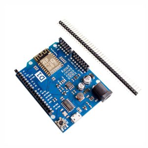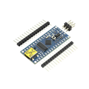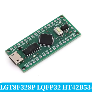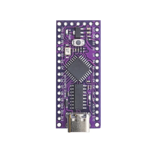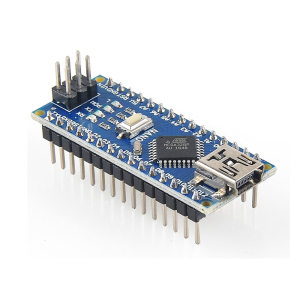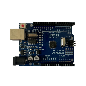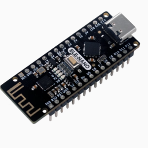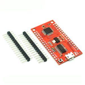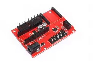
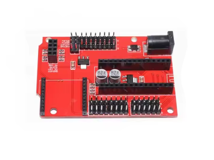
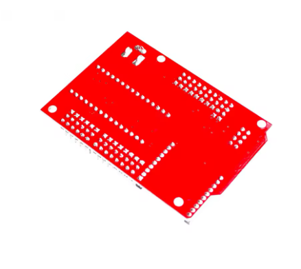
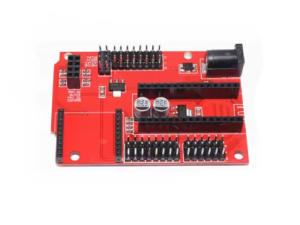
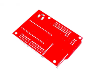
Nano 328P IO sensor wireless expansion board

SKU: FA1070-4
Compatibility

Arduino Nano and 328P-based boards

Microcontroller Support

ATmega328P

Digital I/O Pins

14 pins broken out (including 6 PWM)

Analog Input Pins

8 pins broken out

Wireless Interface

Dedicated module footprint (Bluetooth/Wi-Fi compatible)

Power Input

External DC input for servos and high-current modules

Communication

I2C, UART, and SPI breakout

Board Format

Nano-compatible form factor

The Nano 328P IO Sensor Wireless Expansion Board is a multifunctional add-on designed to expand the capabilities of the Arduino Nano and other 328P-based development boards. It combines organized sensor connectivity with a dedicated interface for wireless communication modules, making it a practical foundation for IoT projects, remote monitoring systems, and connected device prototypes.

At its core, the board reorganizes the Nano’s compact pin layout into convenient three-wire interfaces (Signal, Power, and Ground). This allows sensors and modules to be plugged in directly without the usual tangle of jumper wires. Each pin is clearly labeled, reducing wiring errors and speeding up both prototyping and assembly.

The board also features a dedicated footprint for wireless modules, allowing you to integrate Bluetooth, Wi-Fi, or other wireless communication add-ons directly onto the expansion board. This makes it particularly well suited for IoT applications where the Nano needs to transmit sensor data or receive remote commands.

An independent power input option provides extra current for servos and other high-draw components, helping to isolate the microcontroller’s logic power from heavier loads. This improves stability and protects the development board during operation with motors, relays, and other power-hungry peripherals.

The board is compatible with a wide range of sensors and modules, including temperature and humidity sensors, ultrasonic distance sensors, infrared sensors, and more. Its compact form factor keeps projects organized and portable, while the labeled pins make it easy to identify connections at a glance.

Whether you are building a wireless weather station, a remote-controlled robot, or a smart home sensor node, the Nano 328P IO Sensor Wireless Expansion Board provides a clean, organized platform for your project. It is suitable for individual makers, students, and businesses purchasing in bulk for education, training, or product development.


Features

  • Three-wire pin breakout — Every digital, analog, and power pin is reorganized into convenient Signal-Power-Ground triplets.

  • Wireless module interface — Dedicated footprint for Bluetooth, Wi-Fi, and other wireless communication modules.

  • Independent power input — Separate power supply option for servos and high-current modules.

  • Full pin breakout — All digital, analog, and power pins exposed and clearly labeled.

  • Sensor-friendly layout — Compatible with a wide range of plug-and-play sensor modules.

  • Compact Nano footprint — Preserves the small size of the Nano while adding practical connectivity.

  • Clearly labeled pins — Silkscreen labels match the Nano’s pin names for quick identification.

  • Fully assembled — Ready to use out of the box; no soldering required.


Technical Specifications 

# Parameter Specification
1 Compatibility Arduino Nano and 328P-based boards
2 Microcontroller Support ATmega328P
3 Digital I/O Pins 14 pins broken out (including 6 PWM)
4 Analog Input Pins 8 pins broken out
5 Wireless Interface Dedicated module footprint (Bluetooth/Wi-Fi compatible)
6 Power Input External DC input for servos and high-current modules
7 Communication I2C, UART, and SPI breakout
8 Board Format Nano-compatible form factor

Usage

Getting Started

  1. Mount the Nano — Align the Nano’s pins with the expansion board’s female headers and press firmly to seat. Note the orientation: the Nano’s USB port should face outward.

  2. Connect power — Use USB power from the Nano, or connect an external supply for servos and high-current modules.

  3. Connect sensors — Plug three-wire sensors directly into the labeled Signal-Power-Ground rows. Use I2C, UART, or SPI headers for communication modules.

  4. Install a wireless module — Mount a compatible Bluetooth or Wi-Fi module onto the dedicated footprint and configure it in your sketch.

  5. Upload your sketch — Program the Nano as usual through the Arduino IDE.

Power Options

  • USB power — 5V from the Nano’s USB connection.

  • External DC power — Separate input for servos and high-current modules.

  • Independent power rail — Isolates high-current loads from logic power for improved stability.

Typical Applications

  • IoT sensor nodes — Wireless transmission of sensor data to a central hub or cloud service

  • Wireless weather stations — Remote monitoring of temperature, humidity, and environmental conditions

  • Remote-controlled robots — Wireless command and control for robotic platforms

  • Smart home projects — Connected sensors and actuators for home automation

  • Multi-sensor systems — Connect numerous analog and digital sensors without wiring congestion

  • Data logging — Reliable sensor wiring for long-term monitoring

  • Classroom and STEM education — Organized layout reduces wiring errors and speeds up learning

  • OEM and product development — Standardized connection points for consistent assembly

Notes for Business Buyers

  • Wireless module interface enables rapid IoT prototyping and product development.

  • Organized pin layout reduces assembly time and wiring errors in production and training environments.

  • Independent power capability supports projects with higher power requirements.

  • Suitable for bulk purchasing for educational institutions, R&D teams, and integrators.

Q: Is this expansion board compatible with Arduino Nano?

Yes. It is designed for Arduino Nano and other 328P-based development boards.

Q: What wireless modules can I use with this board?

The dedicated footprint supports common Bluetooth and Wi-Fi modules, as well as other wireless communication add-ons compatible with the Nano’s pinout.

Q: Do I need to solder anything to use this board?

No. The board comes fully assembled with all headers and connectors pre-soldered, ready for immediate use.

Q: How many sensors can I connect simultaneously?

You can connect up to 14 digital devices and 8 analog devices using the three-wire interfaces, plus additional devices via I2C, UART, and SPI.

Q: Can I power servos directly from this expansion board?

Yes. The board includes an independent power input for servos and high-current modules. Use an external DC supply for best results.

Q: What is the purpose of the wireless module footprint?

The footprint provides a dedicated mounting area for Bluetooth or Wi-Fi modules, making it easier to integrate wireless communication into compact Nano projects.

Q: Can I use this board with 3.3V logic sensors?

The board operates at 5V logic. For 3.3V sensors, use appropriate level shifting or check if the sensor is 5V-tolerant.

Q: Is this board suitable for beginners?

Yes. The organized pin layout and clear labeling make it particularly well suited for beginners and educational settings.

Q: Can I stack this expansion board with other shields?

The board is designed with a compact form factor. Stacking with other shields depends on the specific shield’s pin usage and physical dimensions.

Q: Can I purchase in bulk for a school or company?

Yes. This expansion board is suitable for both individual users and business purchasing, including classroom sets, lab equipment, and corporate training programs.