Description
Product Overview
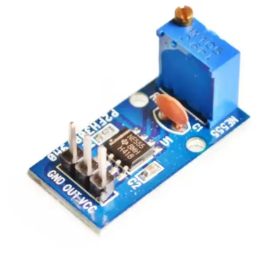
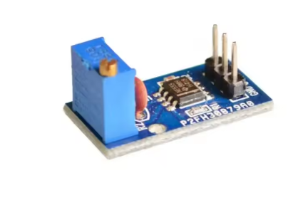
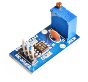
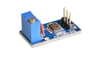
The NE555 Adjustable Frequency Pulse Generator Module is a compact, versatile signal generator built around the legendary NE555 timer IC – one of the most popular and reliable integrated circuits in electronics history. This module generates stable square wave signals with independently adjustable frequency and duty cycle, making it an indispensable tool for electronics experimentation, motor control, and signal generation applications .
At its core is the NE555 timer IC operating in astable (free-running) mode . This configuration allows the module to continuously produce a square wave output without requiring an external trigger signal. Unlike basic fixed-frequency oscillators, this module gives you fine-grained control over both the signal’s speed (frequency) and its on/off ratio (duty cycle) via onboard potentiometers .
The module features a multi-range frequency selector using jumper settings, allowing you to select from four frequency ranges covering approximately 1Hz to over 200kHz . An onboard LED provides real-time visual feedback: it lights up when the output is low, turns off when the output is high, and flashes visibly at lower frequencies – perfect for quick diagnostics without an oscilloscope .
Whether you need a low-frequency pulse for a flashing LED, a mid-range signal for driving a stepper motor driver, or a high-frequency clock for testing digital circuits, this module delivers. With a wide operating voltage range of 5V to 15V DC, it is compatible with both 5V (Arduino, ESP32) and 12V (automotive, industrial) systems .
Key Features
-
Wide Frequency Range: Selectable from four ranges covering approximately 1Hz to over 200kHz, from slow pulses for visual indicators to high-speed signals for digital circuits .
-
Adjustable Duty Cycle: Fine-tune the pulse width (on/off ratio) via the onboard duty cycle potentiometer – essential for PWM motor speed control and servo positioning .
-
Multi-Range Frequency Selection: Four jumper-selectable frequency ranges allow continuous adjustment across decades:
-
1Hz ~ 50Hz: Slow timing, visual indicators
-
50Hz ~ 1kHz: Audio tones, basic motor pulses
-
1kHz ~ 10kHz: Stepper motor drive, PWM applications
-
10kHz ~ 200kHz: High-speed clock generation
-
-
Wide Operating Voltage: Accepts 5V to 15V DC power input, compatible with both 5V (Arduino, ESP32) and 12V (industrial, automotive) systems .
-
LED Output Indicator: Built-in LED provides visual confirmation of output activity – lights on low level, off on high level, flashes visibly at low frequencies .
-
High Output Current: The NE555 can source or sink up to 200mA . The module output current is approximately 15mA at 5V supply and 35mA at 12V supply .
-
Compact Form Factor: Small PCB size (approx. 31mm × 22mm) easily integrates into breadboards, enclosures, or permanent projects .
-
Versatile Output Levels: Output amplitude ranges from approximately 4.2Vpp at 5V input to 11.4Vpp at 12V input .
Technical Specifications
| Parameter | Operating Value |
|---|---|
| Main Chip | NE555 Timer IC |
| Operating Voltage | DC 5V – 15V |
| Input Current | ≥ 100mA (recommended supply capability) |
| Output Current (5V supply) | ~15mA |
| Output Current (12V supply) | ~35mA |
| Maximum Output Current (IC Rating) | 200mA |
| Output Amplitude (5V input) | Approx. 4.2Vpp |
| Output Amplitude (12V input) | Approx. 11.4Vpp |
| Frequency Range | 1Hz – 200kHz (4 selectable ranges) |
| Duty Cycle Range | Approx. 10% – 90% (adjustable) |
| Frequency Determination Formula | T = 0.7 × (RA + 2RB) × C |
| Temperature Stability | 0.005% per °C |
| Dimensions (L × W) | Approx. 31mm × 22mm |
| Output Waveform | Square Wave |
| Output Indicator | LED (lights on low level, flashes at low frequencies) |
| Operating Temperature | -20°C to +70°C |
Reviews
There are no reviews yet.