Product Overview
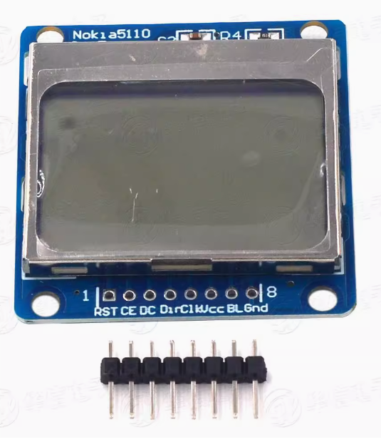
The Nokia 5110 LCD Shield Module is a compact, low-power graphical display module that brings classic mobile phone screen technology to your Arduino projects. Featuring an 84×48 pixel resolution and a vibrant blue backlight, this display is perfect for Arduino, ESP32, and other microcontroller projects requiring clear visual feedback without consuming excessive power or I/O pins .
Originally designed as a replacement screen for the Nokia 5110/3310 mobile phones, this LCD module utilizes the Philips PCD8544 controller chip—the same driver found in the Nokia 3310 LCD . The PCD8544 is a low-power CMOS LCD controller/driver designed to drive a graphic display of 48 rows and 84 columns. All necessary functions for the display are provided in a single chip, including on-chip generation of LCD supply and bias voltages, resulting in a minimum of external components and ultra-low power consumption .
The module communicates via a serial bus interface (SPI) , requiring only 5-6 I/O pins to operate. This makes it ideal for projects where I/O pins are limited. The blue backlight ensures excellent readability even in dim lighting conditions, while the high-contrast LCD provides crisp text and graphics display .
Though it’s an industrial module, this LCD display is extremely easy to use. The module accepts 3-5V input, so no extra level shifter is needed for Arduino compatibility . As a classic display module among open source communities, there are countless related tutorials available over the Internet, making it an ideal choice for beginners and experienced developers alike.
Note: The Nokia 5110 LCD module was discontinued, and many modules on the market are made from recycled screens. Slight blemishes may exist. Please be aware of this before purchasing .
Key Features
-
84×48 Pixel Resolution: Clear display of text, custom graphics, icons, and simple animations with 84 columns by 48 rows of pixels
-
Blue Backlight: Vibrant blue backlight for enhanced visibility in various lighting conditions; backlight can be controlled via GPIO to conserve power
-
Low Power Consumption: Operating current below 200μA with power-down mode support, making it ideal for battery-powered projects
-
SPI Serial Interface: Communicates via standard SPI protocol (SCLK, MOSI, DC, CE, RST), requiring minimal I/O pins (5-6 pins)
-
PCD8544 Controller: Industry-standard LCD controller with on-chip generation of LCD supply and bias voltages
-
Wide Voltage Compatibility: Accepts 3.3V-5V input, compatible with both 3.3V and 5V logic systems without level shifters
-
High Transfer Rate: Supports data transfer rates up to 4Mbps for fast display updates without waiting time
-
Mounting Holes: Pre-drilled mounting holes for secure attachment to enclosures or project boxes
-
Easy-to-Solder PCB: Module is mounted on an easy-to-solder PCB board
-
Wide MCU Compatibility: Works with Arduino, ESP8266, ESP32, STM32, AVR, PIC, MCS51, and other 3.3V/5V logic systems
Technical Specifications
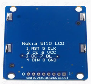
Pinout & Interface Guide
The Nokia 5110 LCD module features 8 pins for connection to your microcontroller :
Important Notes:
-
The LIGHT pin controls the backlight: connecting it to GND turns the backlight ON, connecting to VCC turns it OFF
-
For software-controlled backlight, connect the LIGHT pin to a GPIO pin
-
The display accepts both 3.3V and 5V power, making it compatible with both 3.3V and 5V logic systems
Usage Guide
Hardware Connection (Recommended Wiring)
Based on the LCD5110 library’s default configuration, the recommended connections are :
Software Setup
1. Install the LCD5110 Library
-
Download the LCD5110_Graph library from Rinky-Dink Electronics
-
In Arduino IDE: Sketch → Include Library → Add .ZIP Library
-
Navigate to the downloaded zip file and select it
Alternative: You can also use the Adafruit PCD8544 library available through the Arduino Library Manager.
2. Select Examples
Once installed, navigate to:
The library assumes the following pin connections :
SCK  - Pin 8
MOSI - Pin 9
DC   - Pin 10
RST  - Pin 12
CS   - Pin 11
3. Adjust Pin Configuration (If Needed)
If you’re using different pins, modify the object declaration in your code. The LCD5110 object takes 5 parameters (CLK, DIN, DC, CS, RST) :
LCD5110 myGLCD(8, 9, 10, 11, 12);
Basic Example Code
#include <LCD5110_Graph.h>
LCD5110 myGLCD(8, 9, 10, 11, 12);
extern uint8_t arduino_logo[];
void setup() {
myGLCD.InitLCD();
myGLCD.setFont(SmallFont);
}
void loop() {
myGLCD.clrScr();
myGLCD.drawBitmap(0, 0, arduino_logo, 84, 48);
myGLCD.update();
delay(2000);
myGLCD.clrScr();
myGLCD.print("Nokia 5110", CENTER, 0);
myGLCD.print("84x48 Display", CENTER, 20);
myGLCD.update();
delay(2000);
}
Using the Adafruit PCD8544 Library
Alternative code using the Adafruit library:
#include <SPI.h>
#include <Adafruit_GFX.h>
#include <Adafruit_PCD8544.h>
Adafruit_PCD8544 display = Adafruit_PCD8544(8, 9, 10, 11, 12);
void setup() {
display.begin();
display.setContrast(50);
display.clearDisplay();
display.setTextSize(1);
display.setTextColor(BLACK);
display.setCursor(0, 0);
display.println("Nokia 5110");
display.println("84x48 Display");
display.display();
}
void loop() {
}
Adjusting Display Contrast
The display contrast can be adjusted in software to optimize readability for your specific lighting conditions:
If the display appears too dark, decrease the contrast value; if too light, increase it.
Important Usage Notes
-
Power Supply: The display works with both 3.3V and 5V power
-
Backlight Control: The backlight draws additional current (approximately 10mA). For battery-powered projects, consider controlling the backlight via a GPIO pin to turn it off when not needed
-
Viewing Angle: The LCD has a specific optimal viewing angle; position the display accordingly in your enclosure for best visibility
-
Contrast Adjustment: Different modules may have different optimal contrast settings. Start with a mid-range value (45-50) and adjust until the display is crisp and clear
Q: What types of microcontrollers can I use with this display?
The Nokia 5110 LCD module is compatible with Arduino, ESP8266, ESP32, STM32, AVR, PIC, MCS51, and most other 3.3V/5V microcontrollers .
Q: Can I display graphics and custom characters on this screen?
Yes. With 84×48 pixel resolution, you can display text, custom graphics, icons, simple animations, and even bitmap images. The PCD8544 controller allows pixel-level control .
Q: Is the backlight color only blue?
This specific module features a blue backlight. The blue backlight provides high contrast and excellent visibility in various lighting conditions .
Q: How do I turn the backlight on and off?
The LIGHT pin is active low: connecting it to GND turns the backlight ON, while connecting it to VCC turns it OFF. For software control, connect the LIGHT pin to a GPIO pin and control it programmatically .
Q: What is the maximum SPI speed for this display?
The module supports data transfer rates up to 4 Mbps, allowing fast display updates without waiting time .
Q: Are these modules made from recycled screens?
Yes. The Nokia 5110 LCD module was discontinued, and many modules on the market are made from recycled screens. Slight blemishes may exist. Please be aware of this before purchasing .
Q: Can I power this display from a 5V Arduino?
Yes. The display accepts both 3.3V and 5V power. The module is designed to accept 3-5V input, so no extra level shifter is needed .
Q: Why doesn't my display show anything or shows garbled content?
Common causes include:
-
Loose or incorrect wiring connections
-
Missing or incorrect library installation
-
Wrong pin assignments in code
-
Contrast setting too high or too low
-
Backlight not connected (LIGHT pin to GND)
Q: How do I fix the display if everything appears too dark or too light?
Adjust the contrast setting in your software. In the LCD5110_Graph library, use myGLCD.InitLCD(contrast) where contrast is 0-127 . In the Adafruit library, use display.setContrast(value) where value is 0-100. Try values between 30 and 90.
Q: Can I control the backlight with a PWM pin for dimming?
Yes. You can connect the LIGHT pin to a PWM-capable GPIO pin to control backlight brightness using analogWrite().
Q: What can I build with this Nokia 5110 LCD module?
Popular applications include:
-
Weather stations: Display temperature, humidity, and pressure data
-
Sensor monitors: Real-time display of sensor readings
-
Handheld games: Create simple gaming devices
-
Data loggers: Display logged data and statistics
-
Robotics: Show robot status and debug information
-
Battery-powered projects: Ultra-low power consumption makes it ideal for portable devices
Q: Is this display suitable for battery-powered projects?
Yes, absolutely. With typical operating current under 200μA and power-down mode support, the Nokia 5110 LCD is an excellent choice for portable, battery-powered devices . When the backlight is off, it draws as low as 0.4mA.
Q: What libraries are available for this display?
Popular libraries include:
-
LCD5110_Graph by Henning Karlsen
-
Adafruit PCD8544 (via Arduino Library Manager)
-
Nokia_5110_LCD (lightweight, framebuffer-free)
Q: Where can I find more code examples?
Visit the Arduino IDE’s File → Examples menu after installing the library. The LCD5110 library includes a comprehensive graph demo that showcases drawing text, lines, rectangles, and bitmaps
Q: Can I use this display with ESP32 or ESP8266?
Yes. The display works with ESP32 and ESP8266 boards. Several libraries, including the PCD8544 LCD driver for ESP8266, are available . Just ensure the wiring is correct and adjust the pin assignments in your code accordingly.
Q: What should I do if the screen appears black or the contrast is wrong?
This is usually a contrast issue. As noted in some seller documentation, using a 5V controller on a 3.3V-optimized display can cause the screen to appear black or vague . Try adjusting the contrast setting in software or ensure you’re using the appropriate voltage level for your specific module variant.