Product Overview
The Original L298N Dual H-Bridge Motor Driver Board is a high-performance, rugged, and versatile solution for controlling DC and stepper motors in your robotics, automation, and DIY projects. At its core is the legendary STMicroelectronics L298N integrated circuit, a dual full-bridge driver designed to handle high voltage and high current. This board acts as a powerful interface between your low-voltage microcontroller (like Arduino, Raspberry Pi, STM32, or ESP32) and your high-power motors, allowing you to precisely command motion.
Whether you are building a line-follower robot, a CNC machine, an automated window blind, or an industrial control system, this driver board provides the reliability and simplicity you need. It accepts standard TTL logic levels to control direction and uses Pulse Width Modulation (PWM) for smooth, efficient speed control. The onboard 5V regulator further simplifies your circuit design by providing power to the logic side in many common setups.
Key Features
-
Dual H-Bridge Topology: Based on the robust ST L298N chip, it features two independent H-bridge circuits. This allows you to control the direction and speed of two DC motors simultaneously or drive one bipolar stepper motor.
-
Wide Operating Voltage Range: Accepts a wide motor supply voltage (Vs) from +5V to +35V . This makes it compatible with a vast array of motors, including 5V, 6V, 9V, 12V, and 24V variants.
-
High Output Current: Capable of delivering a continuous 2A of current per channel, with peak currents up to 3A, providing ample power for motors requiring high starting torque .
-
PWM-Compatible Speed Control: Dedicated Enable pins (ENA and ENB) allow for precise speed regulation using PWM signals from your microcontroller. Simply connect these pins to a PWM-capable digital output for smooth acceleration and deceleration .
-
Onboard 5V Regulator (78M05): A convenient onboard voltage regulator can supply the 5V needed for the logic circuitry directly from the motor power supply (provided the motor voltage is between 7V and 12V). This eliminates the need for a separate logic power source in many standard projects .
-
Clear Status Indicators: Features onboard LEDs to indicate power presence and motor direction (A & B), making debugging and operation monitoring straightforward .
-
Built-in Protection Diodes: Includes flyback (snubber) diodes to protect the driver IC from voltage spikes generated by the inductive load of the motors during switching .
-
Robust Screw Terminals: Equipped with large, easy-to-use screw terminals for secure connections to your motors and power supply, ensuring reliability even under vibration.
-
Standard Logic Interface: Control inputs are TTL-compatible (5V logic), allowing for direct connection to most microcontrollers without the need for additional level-shifting circuitry .
Technical Specifications
Pinout and Interface Guide
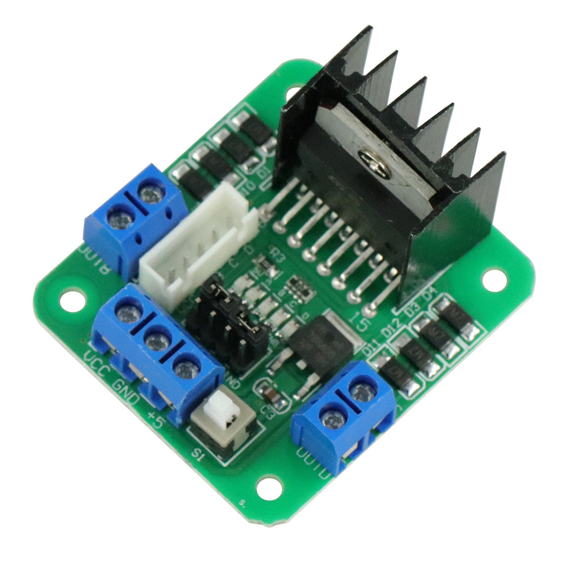
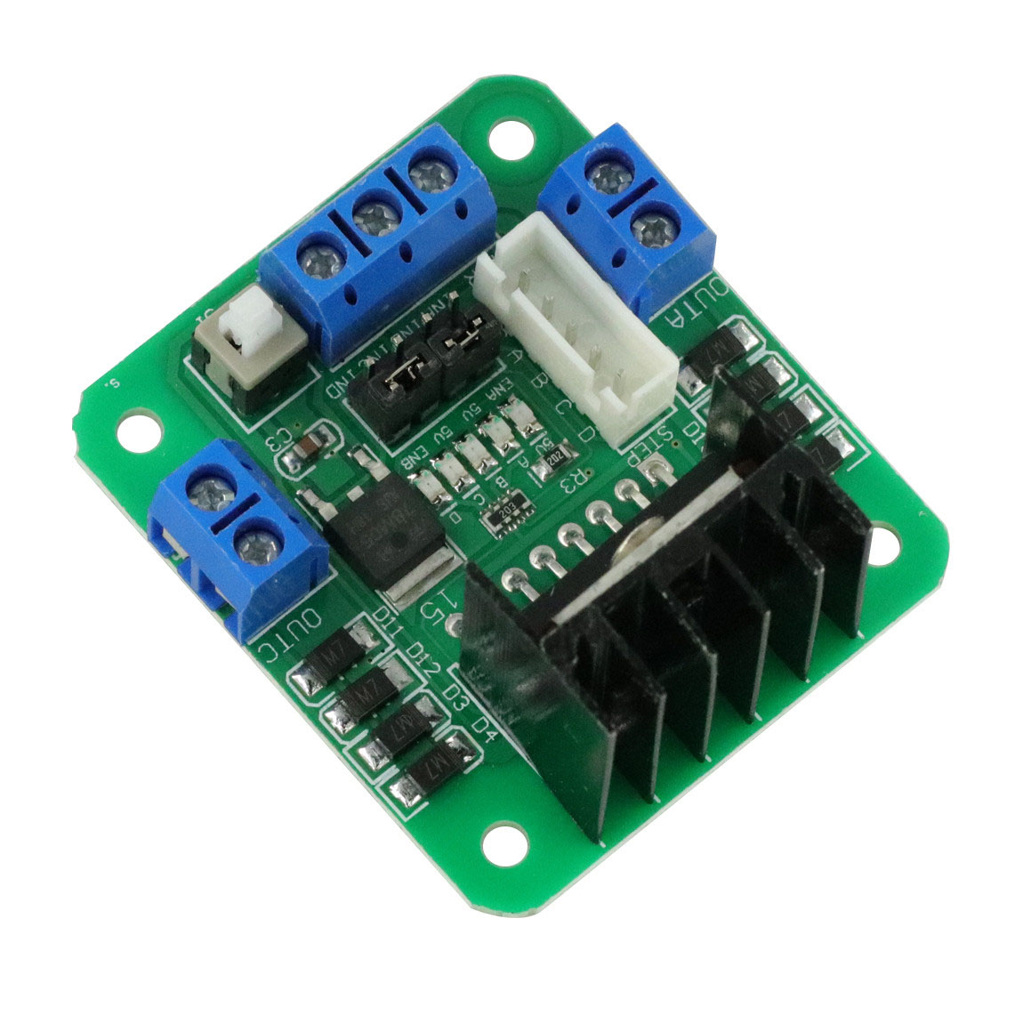
Understanding the pinout is crucial for successful integration. The board is clearly divided into three functional sections.
Power Terminals
-
VCC (+12V/GND): The main screw terminal for motor power. Connect your external power supply (battery or adapter) here. The voltage should match your motor’s rating (5V-35V).
-
GND: The common ground. Crucially, this must be connected to the ground of your microcontroller to create a closed loop for the logic signals .
-
+5V: This pin has a dual function, controlled by the 5V-EN jumper.
-
Jumper ON (7V < VCC < 12V): The pin acts as a 5V OUTPUT, powering the logic circuit from the onboard regulator. You can even use this to power your microcontroller (up to ~500mA).
-
Jumper OFF (VCC > 12V or VCC < 7V): The pin acts as a 5V INPUT. You must supply a regulated 5V to this pin to power the logic side of the board .
Motor Outputs
-
OUT1, OUT2: Terminals for connecting your first DC motor (Motor A) or one coil of a stepper motor.
-
OUT3, OUT4: Terminals for connecting your second DC motor (Motor B) or the second coil of a stepper motor.
Control Pins
-
IN1, IN2: Logic inputs to control the direction of Motor A (e.g., forward, reverse, brake).
-
IN3, IN4: Logic inputs to control the direction of Motor B.
-
ENA: Enable A. Connect this to a PWM-capable pin on your microcontroller to control the speed of Motor A. If a jumper is placed on these pins, the motor runs at full speed (always enabled).
-
ENB: Enable B. Same function as ENA, but for Motor B.
Usage Guide
Typical Wiring to an Arduino (12V Setup)
This is the most common configuration, assuming your motor power supply is 12V.
Control Logic Table
To control a DC motor, use the following logic with your microcontroller:
(The same logic applies to Motor B using ENB, IN3, and IN4)
Important Usage Notes
-
Power Supply: Ensure your motor power supply can provide enough current for your motors (especially during startup). A weak supply can cause erratic behavior or resets.
-
Grounding: Never forget to connect the GND of the L298N to the GND of your microcontroller. This is the single most common cause of “it’s not working” issues.
-
High Voltage Operation: If your motor voltage is above 12V, you MUST remove the 5V-EN jumper. The onboard regulator will overheat and be damaged. You will then need to supply a separate 5V to the +5V pin to power the logic .
-
Heat Dissipation: At currents near 2A, the L298N chip will get hot. The board comes with a heatsink. Ensure adequate airflow. For continuous heavy loads, consider active cooling (a small fan)
Q: What types of motors can I use with this driver?
This driver is designed for brushed DC motors and bipolar stepper motors (typically 4, 6, or 8 wires) . It is not suitable for brushless DC motors (BLDC) or servo motors
Q: Can I control this driver with a 3.3V microcontroller like a Raspberry Pi Pico or ESP32?
Yes, but with caution. The L298N’s logic high threshold is a minimum of 2.3V , so a 3.3V signal is technically within spec. However, for maximum reliability, we recommend using a simple logic level shifter to boost the signals to 5V, or ensure your specific module’s inputs are fully 3.3V compatible.
Q: Can I use this driver to control a 5V DC motor?
Yes. You will need to supply 5V to the VCC terminal. Because 5V is below the 7V needed for the onboard regulator, you MUST remove the 5V-EN jumper and supply a separate, regulated 5V to the +5V pin to power the logic
Q: My motors are weak or stuttering. What could be wrong?
This is often a power issue. Check the following:
-
Power Supply: Your power supply may not be able to deliver enough current for the motors .
-
Grounding: Ensure the L298N’s GND is connected to your microcontroller’s GND .
-
Wiring: Use thicker, shorter wires for the motor power connections to reduce voltage drop .
-
Voltage Drop: The L298N has an internal voltage drop of about 2V. If your motor is rated for 6V, you may need to supply 8-9V to the VCC pin to achieve rated performance at the motor
Q: My microcontroller resets whenever I start the motors. Why?
This is caused by a drop in the power supply voltage due to the high inrush current of the starting motors. Add a large electrolytic capacitor (e.g., 470µF to 1000µF) across the VCC and GND terminals of the L298N to absorb these current spikes . Also, ensure you have a common ground between all components.
Q: The driver gets very hot. Is this normal?
The L298N is a linear driver with bipolar transistors, which are less efficient than modern MOSFET-based drivers. It will get warm during normal operation. However, if it is scorchingly hot, you are likely drawing too much current. Check your motor’s current draw, improve cooling, or reduce the mechanical load on the motor
Q: The LEDs light up, but my motors don't move.
This is a classic sign of a missing enable signal.
-
Check ENA/ENB: Make sure you have a HIGH signal (or a PWM signal) on the ENA/ENB pins. If the jumpers are still on these pins, they are enabled. If you removed the jumpers, your microcontroller must send a signal .
-
Check Wiring: Ensure your motor wires are firmly clamped in the screw terminals .
-
Check IN Pins: Verify you are sending the correct HIGH/LOW signals to the IN pins.
Q: My motors only spin in one direction.
Double-check your wiring of the IN1/IN2 and IN3/IN4 pins to your microcontroller. Also, verify your code is correctly changing the states of these pins to create the forward and reverse logic conditions (e.g., HIGH/LOW vs. LOW/HIGH).
Q: The board stopped working and now smells burnt. What happened?
The most common causes are:
-
Short Circuit: A short across the motor output terminals.
-
Over-voltage on Logic: Applying more than 7V to the +5V pin (or leaving the 5V-EN jumper on with a motor supply > 12V) .
-
Excessive Current: Drawing significantly more than 2A for an extended period without adequate cooling.