Suggested Reading
Before delving into this tutorial, here are some concepts you should be familiar with. If you’re not, consider checking out the related tutorial first.
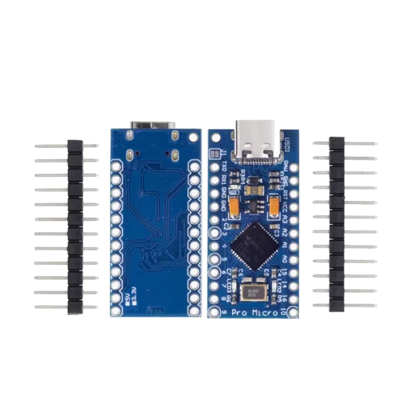
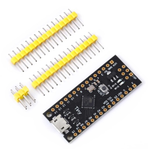
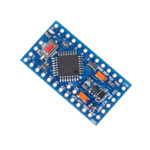
Pinouts
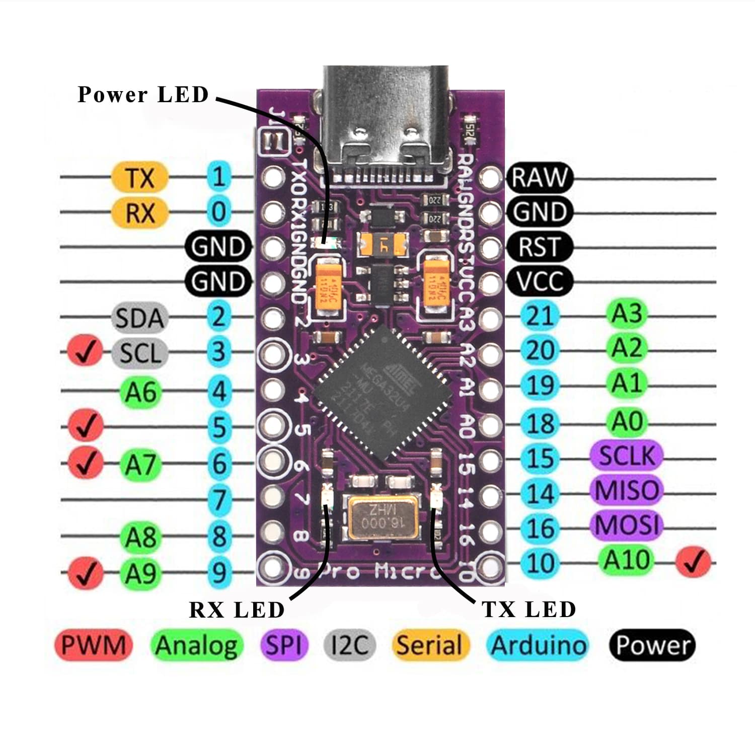
There are a variety of power and power-related nets broken out:
- RAW is the unregulated voltage input for the OSOYOO Pro Micro. If the board is powered via USB, the voltage at this pin will be about 4.8V (USB’s 5V minus a Schottkey diode drop). On the other hand, if the board is powered externally, through this pin, the applied voltage can be up to 12V.
- VCC is the voltage supplied to the on-board ATmega32U4. This voltage will depend on whether you’re using a 3.3V/8MHz OSOYOO Pro Micro or a 5V/16MHz version, it’ll be either 3.3V or 5V respectively. This voltage is regulated by the voltage applied to the RAW pin. If the board is powered through the ‘RAW’ pin (or USB), this pin can be used as an output to supply other devices.
- RST can be used to restart the OSOYOO Pro Micro. This pin is pulled high by a 10k&Ohm; resistor on the board, and is active-low, so it must be connected to the ground to initiate a reset. The OSOYOO Pro Micro will remain “off” until the reset line is pulled back to high.
- GND, of course, is the common, ground voltage (0V reference) for the system.
I/O Pins
The OSOYOO Pro Micro’s I/O pins – 18 in all – are multi-talented. Every pin can be used as a digital input or output, for blinking LEDs or reading button presses. These pins are referenced in the Arduino IDE via an integer value between 0 and 21. (The A0-A3 pins can be referenced digitally using either their analog or digital pin number).
Nine pins feature analog to digital converters (ADCs) and can be used as analog inputs. These are useful for reading potentiometers or other analog devices using the analogRead([pin]) function.
There are five pins with pulse width modulation (PWM) functionality, which allows for a form of analog output using the analogWrite([pin], [value]) function. These pins are indicated on-board with a faint, white circle around them.
There are hardware UART (serial), I2C, and SPI pins available as well. These can be used to interface with digital devices like serial LCDs, XBees, IMUs, and other serial sensors.
The OSOYOO Pro Micro has five external interrupts, which allow you to instantly trigger a function when a pin goes either high or low (or both). If you attach an interrupt to an interrupt-enabled pin, you’ll need to know the specific interrupt that pin triggers: pin 3 maps to interrupt 0, pin 2 is interrupt 1, pin 0 is interrupt 2, pin 1 is interrupt 3, and pin 7 is interrupt 4.
On-Board LEDs
There are three LEDs on the OSOYOO Pro Micro. One green LED indicates whether power is present.
The other two LEDs help indicate when data is transferring over USB. One LED represents USB data coming into (RX) the the OSOYOO Pro Micro, and the other LED indicates USB data going out (TX).