Product Overview
The PWM DC Motor Speed Controller (12-40V 10A) is a rugged, high-performance speed regulation module designed for precise and efficient control of brushed DC motors. Using advanced Pulse Width Modulation (PWM) technology , this controller provides smooth, stepless speed adjustment from 0% to 100% by varying the duty cycle of the voltage delivered to your motor .
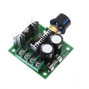
This controller is built for demanding applications, capable of handling a wide input voltage range of 12V to 40V DC and delivering up to 400W of power to your load . It features a robust aluminum mounting bracket for secure and stable installation in control panels, machinery, or custom enclosures, ensuring the module stays firmly in place even in high-vibration environments.
Unlike simple resistive controls, this PWM controller maintains high torque even at low speeds, ensuring your motor doesn’t lose power when you need it most . Built-in protection features, including a replaceable 10A fuse, reverse polarity protection, and over-voltage protection, safeguard both the controller and your equipment from common electrical faults .
This controller is the ideal choice for a vast array of applications, including:
-
Conveyor belt speed regulation
-
Industrial automation and machinery
-
DIY workshop tools (drill presses, lathes)
-
Robotics and animatronics
-
Electric vehicle prototypes (golf carts, e-bikes)
-
Pump and fan speed control
-
Laboratory and testing equipment
Key Features
-
Wide Input Voltage Range: Accepts DC input from 12V to 40V, making it compatible with a vast range of common power supplies, batteries (12V, 24V, 36V), and industrial DC sources .
-
High Power Capacity: Capable of handling loads up to 400W (10A at 40V) . For continuous operation, the rated current is 8A, with a maximum peak current of 10A protected by an onboard fuse .
-
Smooth PWM Speed Control: Utilizes high-frequency PWM (13kHz) to provide stepless, vibration-free speed adjustment from 0% to 100% using the onboard potentiometer knob . The high frequency also minimizes audible motor noise.
-
High Torque at Low Speeds: Unlike voltage regulators, PWM control maintains excellent motor torque even at the lowest speed settings, ensuring your motor has the power to start and turn loads effectively .
-
Integrated Mounting Bracket: Includes a sturdy metal mounting bracket that allows for secure and professional installation onto flat surfaces, panels, or within equipment racks.
-
Comprehensive Protection Features:
-
10A Fuse: A standard, user-replaceable 5x20mm fuse provides overload and short-circuit protection .
-
Reverse Polarity Protection: Safeguards the controller from accidental reverse connection of the power supply .
-
Over-Voltage Protection: Prevents damage from excessive input voltage .
-
Low Standby Current: Consumes only 0.02A (20mA) when idle, minimizing power draw when the motor is not running .
-
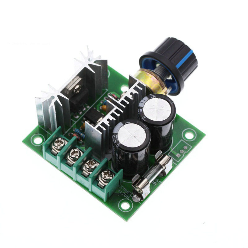
Easy Wiring: Features large, clear screw terminals for secure connections to your power supply and motor. A simple potentiometer knob provides intuitive speed control .
-
Rugged Construction: Built with high-quality electronic components and housed in a durable case (approx. 60x55x28mm) , designed for long-term reliability in industrial environments .
-
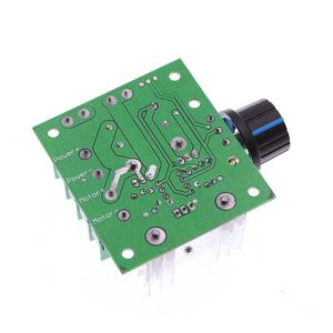
External Control Capability: Includes a 3-pin header for connecting an external potentiometer, allowing you to mount the speed control knob remotely from the main unit for flexible panel design .
Technical Specifications
Pinout & Interface Guide
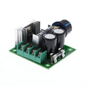
The controller features clearly labeled screw terminals for all power connections.
Power Terminals
-
Power Input (IN + / IN -): Connect your DC power supply (12-40V) here. Observe correct polarity (+ to +, – to -) . Reversing this connection, even momentarily, can damage the controller despite the protection features .
-
Motor Output (OUT + / OUT -): Connect your brushed DC motor here. If the motor runs in the opposite direction to what you expect, simply swap these two wires .
Control Interface
-
Onboard Potentiometer: The large knob on the controller provides intuitive, stepless speed adjustment. Turning clockwise increases motor speed; counter-clockwise decreases it.
-
External Potentiometer Header (3-pin): This connector allows you to wire in an external potentiometer (typically B100K) for remote speed control. To use this, you would typically remove the onboard potentiometer or configure a switch .
Status Indicators
Usage Guide
Important Safety Warnings
-
DC ONLY: This controller is designed strictly for DC circuits. Never connect it to AC mains power (e.g., 110V or 220V AC). Doing so will instantly destroy the controller and poses a serious fire hazard .
-
Motor Type: This controller is for brushed DC motors only . It is NOT compatible with brushless DC motors (BLDC) or single-phase AC motors .
-
Polarity: Always double-check your power supply connections for correct polarity before applying power. Incorrect polarity can damage the controller .
-
Current Limits: For continuous operation, do not exceed the 8A continuous current rating. The 10A fuse is for peak and short-circuit protection; sustained operation at 10A may cause overheating.
-
Secure Mounting: Use the included mounting bracket to securely fasten the controller, preventing movement and potential short circuits.
Wiring Guide
Step-by-Step Operation
-
Mount the Controller: Secure the module to a panel or surface using the provided mounting bracket.
-
Connect the Motor: Connect your DC motor to the OUT + and OUT – terminals.
-
Connect the Power Supply: Connect your DC power supply to the IN + and IN – terminals. Ensure the power supply is turned OFF or disconnected during wiring .
-
Set Initial Speed: Turn the potentiometer knob fully counter-clockwise to its lowest setting.
-
Apply Power: Turn on your DC power supply. The motor should remain off or at its lowest speed.
-
Adjust Speed: Slowly turn the potentiometer knob clockwise. The motor will begin to spin and increase in speed as you turn. Adjust until you reach the desired speed.
-
Change Direction (if needed): To reverse the motor’s direction, turn off the power, swap the two motor wires at the OUT + and OUT – terminals, and then reapply power .
Q: What types of motors can I use with this controller?
This controller is designed for brushed DC motors only . It works with common 12V, 24V, and 36V DC motors, including the popular 775 series . It is not suitable for brushless motors (BLDC) or AC motors.
Q: Can this controller change the direction of my motor?
This specific model provides speed control only. It does not have a direction switch. However, you can easily change the motor’s direction by swapping the two motor wires at the OUT + and OUT – terminals . Always turn the power off before doing this.
Q: What is the difference between this PWM controller and a simple voltage regulator?
A PWM controller switches the power on and off very rapidly (13,000 times per second) to control speed . This method is far more efficient and maintains high motor torque even at low speeds. A simple voltage regulator would reduce torque along with speed, causing the motor to stall easily
Q: Can I use this with a 12V or 24V battery?
Yes, absolutely. The 12-40V input range makes it perfect for use with 12V, 24V, and even 36V battery banks
Q: What is the real-world current limit for this controller?
The controller is rated for a continuous output current of 8A. The maximum current, protected by a 10A fuse, is 10A . For long-term reliability, it’s best to design your system to operate continuously at 8A or less.
Q: What power supply should I use?
Use a DC power supply or battery bank with a voltage between 12V and 40V. The power supply must be capable of delivering at least the current your motor will draw (up to 8A continuous). For example, for a motor that draws 5A at 24V, a 24V 6A or 8A power supply is recommended.
Q: The controller gets warm. Is this normal?
Yes, some warmth is normal when switching higher currents. The module is designed to dissipate this heat. However, if it becomes too hot to touch, you may be exceeding the current rating or have inadequate ventilation.
Q: My motor runs weakly or stops at low speeds. What's wrong?
This can happen if the motor is not getting enough voltage or if the PWM frequency is too high for that specific motor. However, this controller is designed to maintain torque. Check that your power supply voltage matches your motor’s rating and that you are not exceeding the current limit. If the problem persists, the motor itself may be faulty.
Q: The controller doesn't work. The motor doesn't move.
Follow this checklist:
-
Check the Fuse: The most common issue. Remove the fuse and check if the internal wire is broken. If so, replace it with another 5x20mm 10A fuse .
-
Check Power: Verify with a multimeter that you have the correct DC voltage at the IN + and IN – terminals.
-
Check Polarity: Ensure your power supply is connected with the correct polarity (+ to +, – to -) .
-
Check Connections: Ensure all wires are securely fastened in the screw terminals.
-
Test the Motor: Connect your motor directly to the power supply (briefly) to ensure it works.
Q: The motor runs at full speed all the time, and the knob doesn't control it.
This indicates that the MOSFET switching element may have failed “shorted.” This can happen if the controller was overloaded or experienced a short circuit. You will likely need to replace the controller.
Q: Can I control this with a microcontroller like an Arduino?
This specific model is designed for manual control via a knob. To control it with an Arduino, you would need to replace the onboard potentiometer with a digital potentiometer or use a different type of controller. The 3-pin header is for an external potentiometer, not a direct logic signal
Q: What is the 3-pin white connector for?
This is an interface for connecting an external potentiometer (typically a B100K) . This allows you to mount the speed control knob remotely, on a front panel for instance, away from the main controller board.
Q: Does it have a switch to turn it on and off?
No, it does not have an integrated on/off switch. Power is controlled by turning your main power supply on or off.