Product Overview
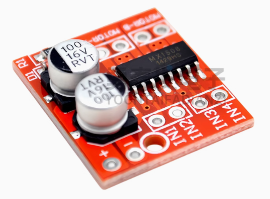
The SmartDrive Mini L298N 2-Channel Motor Controller is a compact yet powerful dual H-Bridge driver designed for space-constrained robotics and DIY projects. While based on the reliable H-Bridge principle, this “Mini” version upgrades the traditional design by utilizing low on-resistance MOS switches instead of traditional bipolar transistors. This results in significantly lower heat generation, eliminating the need for bulky heatsinks in most applications .
This module serves as the perfect interface between your microcontroller (Arduino, Raspberry Pi Pico, STM32, ESP32) and your motors. It accepts standard logic-level signals to control direction and uses Pulse Width Modulation (PWM) for smooth, efficient speed control. Whether you are building a compact line-follower robot, a smart car, or a battery-powered toy, the SmartDrive Mini delivers robust performance in a tiny footprint .
Key Features
-
Dual-Channel H-Bridge: Independently control the direction and speed of two DC motors, or drive one bipolar stepper motor .
-
Compact & Lightweight Design: With dimensions of just 24.7mm x 21mm, this module is ideal for projects where space is at a premium .
-
MOSFET-Based Efficiency: Utilizes advanced MOS switches with low circuit resistance. This design runs cooler, requires no external heatsink, and is more power-efficient than traditional L298N linear driver boards .
-
PWM Speed Control: Dedicated enable pins allow for precise speed regulation via PWM signals from your microcontroller, giving you smooth acceleration and deceleration.
-
Integrated Thermal Protection: Features a built-in thermal protection circuit with hysteresis (TSD). If the motor stalls or the module overheats, the driver safely shuts down and automatically recovers once the temperature drops .
-
Wide Logic Compatibility: Signal input voltage range of 1.8V to 7V makes it compatible with both 5V and 3.3V microcontrollers without requiring level shifters .
-
Fail-Safe Inputs: Built-in common-mode conduction circuit ensures the motor does not malfunction when the input pins are left floating .
-
Low Standby Current: Consumes less than 0.1uA in standby mode, preserving battery life in portable applications .
Technical Specifications
Pinout & Interface Guide
The Mini L298N is designed for simple, direct integration.
Power & Motor Terminals
-
Vm / GND: Main screw/pin terminals for motor power. Connect your battery or external power supply (2V-10V) here.
-
Motor A Outputs: Terminals for connecting your first DC motor or one coil of a stepper motor.
-
Motor B Outputs: Terminals for connecting your second DC motor or the second coil of a stepper motor.
Control Pins
-
IN1, IN2: Logic inputs to control the direction of Motor A.
-
IN3, IN4: Logic inputs to control the direction of Motor B.
-
ENA: Enable/PWM input for Motor A. Connect to a PWM-capable pin on your microcontroller to control speed.
-
ENB: Enable/PWM input for Motor B. Same function as ENA.
*(Note: Unlike the traditional large L298N board, this Mini version typically does not include an onboard 5V regulator or power selection jumpers, as it is designed for low-voltage operation directly from the motor supply.)*
Usage Guide
Typical Wiring to an Arduino (5V Setup)
Control Logic Table
(Same logic applies to Motor B using ENB, IN3, and IN4)
Important Usage Notes
-
Power Supply: Ensure your motor power supply voltage is within the 2V-10V range. Operating above 10V can permanently damage the module .
-
Grounding: Never forget to connect the GND of the module to the GND of your microcontroller. This is essential for a closed control loop.
-
Current Limits: While the module can handle 1.5A continuously per channel, ensure your motors do not continuously draw peak current (2.5A) for extended periods to avoid triggering the thermal protection.
Q: What is the difference between this "Mini" L298N and the "Original" large L298N board?
The main differences are size and technology.
-
Size: The Mini is significantly smaller (24.7mm x 21mm) .
-
Technology: The Original large board uses bipolar transistors which run hot and require a heatsink. The Mini version uses MOS switches, which are more efficient, generate less heat, and do not need a heatsink .
-
Voltage: The Mini operates at a lower voltage range (2V-10V), making it ideal for battery-powered toys, whereas the large board handles up to 35V
Q: What types of motors can I use with this driver?
This driver is designed for brushed DC motors (two of them) and bipolar stepper motors (one 4-wire stepper) . It is not suitable for brushless DC motors (BLDC) or servo motors.
Q: Can I use this with a 3.3V microcontroller like an ESP32 or Raspberry Pi Pico?
Yes, absolutely. The signal input voltage range is 1.8V to 7V, making it directly compatible with 3.3V logic without any additional level shifters
Q: My 5V motors are running weak. What could be wrong?
-
Power Supply: Check that your battery pack can supply enough current (at least 1A per motor).
-
Voltage Drop: Ensure your power supply is actually delivering close to 5V under load. Thin wires or a dying battery can cause significant voltage drop.
Q: The module gets warm. Is this normal?
While this Mini version runs much cooler than the traditional L298N due to its MOS design, it can still get slightly warm under continuous 1.5A load. However, if it gets hot to the touch, you may be drawing too much current or stalling a motor. The thermal protection circuit will shut it down if it overheats
Q: The motor stopped working but the module seems fine. Did it break?
Probably not. Check if the thermal protection was triggered.
-
If a motor stalled or was overloaded, the internal temperature may have risen above the safe limit. The module will automatically shut down the outputs to protect itself. Once it cools down (temperature drops), it will automatically resume operation
Q: The motors don't move. What should I check?
-
Check Enable Pins: Ensure ENA/ENB are connected to a HIGH signal or a PWM source. If left floating, the motors will not move.
-
Check Power: Verify the voltage at the Vm pin is between 2V and 10V.
-
Check Grounding: Confirm that the module’s GND is connected to your microcontroller’s GND.
-
Check Inputs: Ensure your code is setting IN1/IN2 (or IN3/IN4) to opposite states (HIGH/LOW or LOW/HIGH) and not the same state (which would cause braking).
Q: The module has a very low standby current. Do I need a power switch?
The module consumes less than 0.1uA when the motors are off but the power is still connected . For most battery-powered projects, this is negligible, and you may not need a dedicated on/off switch unless you are storing the device for months at a time.